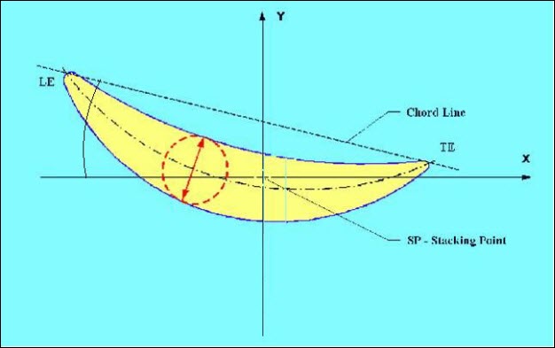
This parameter is the chord line angle in the section plane after the user-defined bestfit.
The angle convention in PC-DMIS Blade is positive CCW (looking in the Z minus direction).
The actual chord line after bestfit is compared to the nominal chord line. This angle may be different than the twist angle because the nose and tail points can change when the camber of the blade changes.
The chord angle can be measured relative to a reference section. See "Relative Calculations".
The chord angle in the graphic below is the angle between the chord line and the XAXIS.

Example of chord angle
Comparison of the Chord Angle Methods
The chord angle is always the measure of the sweep from the positive X axis to the "chord line vector". The chord line vector is always the direction between two determined points. The determination of these two points depends on the method. The vector (direction) of the chord line is defined from the first point to the second point.
| Method | First Point | Second Point |
NOSETAIL |
Nose point (projected intersection of MCL and LE). |
Tail point (projected intersection of MCL and TE). |
CALIPER |
Find the line that will touch the CCV curve in two places; this point is the touch point closer to the LE. |
Find the line that will touch the CCV curve in two places; this point is the touch point closer to the TE. |
LE_DIST |
Create a line from the nose point to the tail point. Create a point that is on this line and its distance from the nose point is gage offset 1. A line is created that passes through this point and is perpendicular to the chord line. This line is intersected with the CCV side to determine the first point. |
Create a line from the nose point to the tail point. Create a point that is on this line and its distance from the nose point is gage offset 2. A line is created that passes through this point and is perpendicular to the chord line. This line is intersected with the CCV side to determine the second point. |
LE_TE |
Create a line from the nose point to the tail point. Create a point that is on this line and its distance from the nose point is gage offset 1. A line is created that passes through this point and is perpendicular to the chord line. This line is intersected with the CCV side to determine the first point. |
Create a line from the nose point to the tail point. Create a point that is on this line and its distance from the tail point is gage offset 2. A line is created that passes through this point and is perpendicular to the chord line. This line is intersected with the CCV side to determine the second point. |
STACK |
Create the line from the nose point to the tail point. Project the stack point (origin) onto this line. Create a point that is on the line and its distance from the projected stack point is gage offset 1. This point is toward the LE. A line is created that passes through this point and is perpendicular to the chord line. This line is intersected with the CCV side to determine the first point. |
Create the line from the nose point to the tail point. Project the stack point (origin) onto this line. Create a point that is on the line and its distance from the projected stack point is gage offset 2. This point is toward the TE. A line is created that passes through this point and is perpendicular to the chord line. This line is intersected with the CCV side to determine the second point. |