
Auto Cone button
The Cone auto option allows you to define a cone measurement. This measurement type is particularly useful when equal spacing of the hits is necessary for partial cones. The minimum number of hits needed to measure an auto cone is six.
To access the Cone option, access the Auto Feature dialog box for a Cone (Insert | Feature | Auto | Cone).
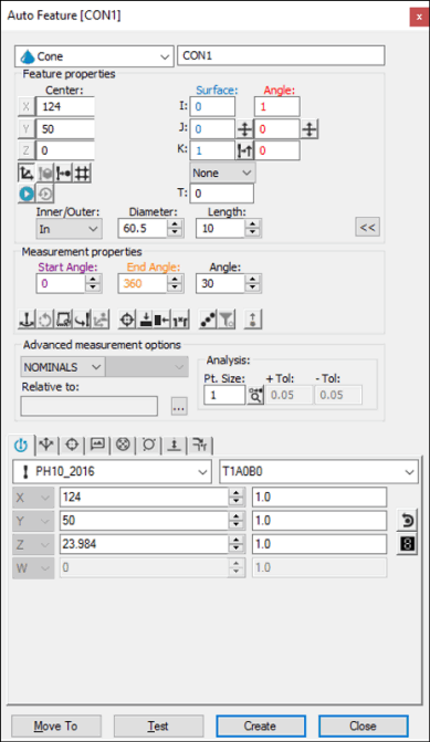
Auto Feature dialog box - Cone
With the dialog box open, use one of these methods to create the feature.
On the methods below, an external cone (stud) from versions 3.6 and before may need to have its vectors and length negated to correctly measure.
Using Surface Data on the Screen
To generate a cone using surface data:
From the Graphic Modes
toolbar, click the Surface Mode icon ( ).
).
Position the mouse pointer (outside or inside the desired cone).
Click once on the cone's surface. PC-DMIS highlights the selected cone. The dialog box displays the center point, angle, and diameter from the CAD data of the selected cone.
Make any other modifications to the dialog box as needed.
Click Create.
Using Surface Data with the CMM
You should select the Find Noms option in the Mode list for this measurement method. For more information on nominals, see the "Mode List" topic in the PC-DMIS Core documentation.
To generate a cone using surface data with the CMM:
Take three hits in the hole or on the stud.
Move the probe to another depth.
Take three additional hits. PC-DMIS pierces the CAD surface closest to where the probe touched.
The displayed X, Y, Z values reflect the closest CAD cone, not the actual hits. The I, J, K reflects the surface normal vector. If a CAD cone is not found, PC-DMIS displays the closest point and asks you to take the additional hits.
Using Wireframe Data on the Screen
Wireframe CAD data can also be used to generate a cone.
To generate the cone using wireframe data:
Click near the desired wire on the cone. PC-DMIS highlights the selected wire. This gets the cone center, surface vector, and diameter.
Click on a second wire that represents the other end of the cone to calculate the angle.
The probe approach is always perpendicular to the feature, as well as perpendicular to the current probe centerline vector. The dialog box displays the value of the selected cone's center point and diameter once the wire has been indicated.
If the underlying CAD element is not a cone, circle, or arc, additional clicks may be necessary to identify the feature. If PC-DMIS doesn't highlight the correct feature, try to click on at least two additional locations on the cone.
Without Using CAD Data
To generate the cone without using CAD data:
Take three hits on the surface to find the plane that the cone is lying in.
Take three hits in the hole (or on the stud) at the same level.
Take at least one hit at either a lower or higher level than the first three hits (take up to three hits to get an accurate definition of the cone).
Typing the Data
This method allows you to type the desired X, Y, Z, I, J, K values for the cone.
Type the desired X, Y, Z, I, J, K values for the feature into the dialog box.
Click Create to insert the feature into your measurement routine.