
Auto Corner Point button
The Corner Point auto option allows you to define a point measurement that is the intersection of three measured planes. You can do this without measuring the planes separately and constructing an intersection point. You must take nine hits (three hits on each of the three planes) to measure a corner point.
To access the Corner Point option, access the Auto Feature dialog box for a Corner Point (Insert | Feature | Auto | Point | Corner).
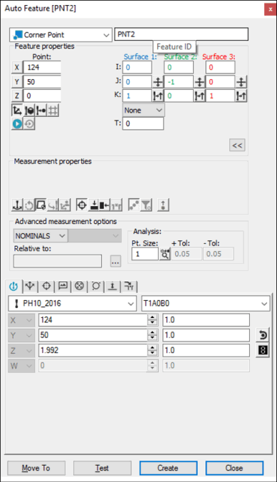
Auto Feature dialog box - Corner Point
With the dialog box open, use one of these methods to create the feature.
Using Surface Data on the Screen
To generate a corner point using surface data:
From the Graphic Modes
toolbar, click the Surface Mode icon ( ).
).
Click once near the corner. You'll notice PC-DMIS automatically re-positions the animated probe on the corner point.
Verify that the correct corner point is selected. The dialog box displays the value of the selected corner point and vector once the point has been indicated.
Make any other modifications to the dialog box and the Probe Toolbox as needed.
Click Create.
Using Surface Data with the CMM
To generate a corner point using surface data with the CMM:
Touch once on each of the three surfaces that converge on the corner. PC-DMIS assumes that the surfaces are mutually perpendicular.
Make any other modifications to the dialog box and the Probe Toolbox as needed.
Click Create.
If the CAD corner point is not found, PC-DMIS displays the closest point and asks you to take the additional hits.
You should select the Find Noms option in the Mode list for this measurement method. For more information on nominals, see the "Mode List" topic in the PC-DMIS Core documentation.
Using Wireframe Data on the Screen
Wireframe CAD data can also be used to generate a corner point.
To generate the point:
Click once near (but not on) the corner. PC-DMIS highlights the selected surface.
Verify that the correct surface has been selected. The dialog box displays the value of the selected corner point and vector once the point has been indicated. (If necessary, click on a different edge, leading into the corner.)
Make any other modifications to the dialog box and the Probe Toolbox as needed.
Click Create.
Using Wireframe Data with the CMM
To generate a corner point using wireframe data with the CMM:
Touch twice on the first surface.
Touch once near the edges that converge on the corner. PC-DMIS assumes that the surfaces are mutually perpendicular. If the CAD corner point is not found, PC-DMIS displays the closest point and asks that you take the additional hits.
Make any other modifications to the dialog box and the Probe Toolbox as needed.
Click Create.
You should select the Find Noms option in the Mode list for this measurement method. For more information on nominals, see the "Mode List" topic in the PC-DMIS Core documentation.
Without Using CAD Data
To generate a corner point without the use of CAD data:
Touch three times on the first surface.
Touch two times on the second surface.
Touch once on the third surface.
Make any other modifications to the dialog box and the Probe Toolbox as needed.
Click Create.
Typing the Data
This method allows you to type the desired X, Y, Z, I, J, K values for the corner point.
Type the desired X, Y, Z, I, J, K values for the feature into the dialog box.
Click Create to insert the feature into your measurement routine.