
Auto Edge Point button
The Edge Point auto option allows you to define a point measurement that is to be taken on the part's edge. This measurement type is particularly useful when the part's material is thin enough that a precisely controlled CMM measurement hit is required. Five sample hits are needed to accurately measure an edge point.
To access the Edge Point option, open the Auto Feature dialog box for an Edge Point (Insert | Feature | Auto | Point | Edge).
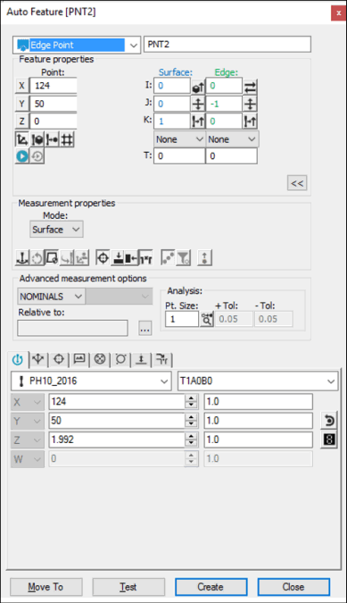
Auto Feature dialog box - Edge Point
With the dialog box open, use one of these methods to create the feature:
Using Surface Data on the Screen
To generate an edge point using surface data:
From the Graphic Modes
toolbar, click the Surface Mode icon ( ).
).
Click once on the surface near the edge where you want to create the Auto Edge Point.
Verify that the correct surface has been selected.
The dialog box displays the value of the selected edge point and vector
once the point has been indicated. The direction of the surface normal
vector is determined by the side of the part that is accessible to
the probe. If both sides of the part are equally accessible, the normal
from the CAD data is used. The Flip Vector
icon ( ) on the dialog box lets you change the direction
of the approach.
) on the dialog box lets you change the direction
of the approach.
Click Create to insert the feature into the measurement routine. If additional mouse clicks are detected before you click the Create button, PC-DMIS overwrites the previous information with the new data.
Using Surface Data with the CMM
To generate an edge point using surface data with the CMM:
Touch near the desired edge of the part using the probe.
Try to make the shank as normal to the surface as possible.
PC-DMIS pierces the CAD surface closest to where the probe touched. The displayed X, Y, and Z values reflect the closest CAD edge to the hit, not the actual hit. The I, J, K reflects the surface normal vector.
If a CAD edge is not found, PC-DMIS displays the closest point and asks you to take the additional hits.
If a second touch is taken on the opposite surface prior to clicking the Create button, PC-DMIS alters the location values as appropriate. The displayed vectors, however, remain constant.
You should select the Find Noms option in the Mode list for this measurement method. For more information on nominals, see the "Mode List" topic in the PC-DMIS Core documentation.
Using Wireframe Data on the Screen
You can also use wireframe CAD data to generate an edge point.
To generate an edge point:
Click near the desired wire on the edge side (not within the boundary of the top surface). PC-DMIS highlights the selected wire.
Verify that the correct feature has been selected.
The probe approach is always perpendicular to the line, as well as perpendicular to the current probe centerline vector. The probe approaches from the side of the edge that was clicked on. The dialog box displays the value of the selected edge point and the vector once the wire has been indicated.
If an additional touch is necessary, click on the opposite wire of the (normal) surface.
Using Wireframe Data with the CMM
To generate an edge point using wireframe data with the CMM:
Touch near the desired edge of the part using the probe.
Try to make the shank as normal to the surface as possible.
PC-DMIS pierces the CAD wire closest to where the probe touched. The displayed X, Y, Z values reflect the closest CAD edge to the hit, not the actual hit. The I, J, K reflects the surface normal vector. If a CAD edge is not found, PC-DMIS displays the closest point and asks you to take the additional hits.
If a second touch is taken on the opposite surface prior to clicking the Create button, PC-DMIS alters the location values as appropriate. The displayed vectors, however, remain constant.
You should select the Find Noms option in the Mode list for this measurement method. For more information on nominals, see the "Mode List" topic in the PC-DMIS Core documentation.
Without Using CAD Data
If the edge point is to be generated without the use of CAD data:
The first three hits that are taken indicate the surface vector nominal.
The next two hits find and display the other vector. This value indicates the opposite direction of the CMM approach vector (pointing away from the surface).
The last hit (sixth hit) indicates the actual edge point location.
Typing the Data
This method allows you to type the desired X, Y, Z, I, J, K values for the edge point.
Type the desired X, Y, Z, I, J, K values for the feature into the dialog box.
Click Create to insert the feature into your measurement routine.