
Auto Ellipse button
The Ellipse auto option allows you to define an ellipse. The ellipse feature type works much like the sheet metal circle feature. It is particularly useful when the ellipse is positioned in a specific plane that is not parallel with any of the workplanes. It is also useful if equally spaced hits are required for partial ellipses. The minimum number of hits required to measure an ellipse is five.
To access the Ellipse option, access the Auto Feature dialog box for an Ellipse (Insert | Feature | Auto | Ellipse).
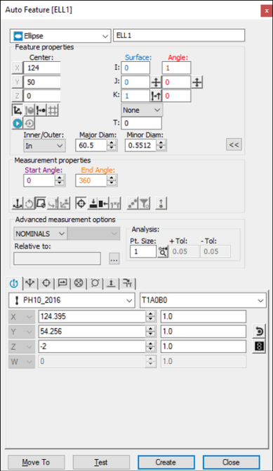
Auto Feature dialog box - Ellipse
With the dialog box open, use one of these methods to create the feature.
Using Surface Data on the Screen
From the Graphic Modes
toolbar, click the Surface Mode icon ( ).
).
Click once on the ellipse displayed in the Graphic Display window. PC-DMIS computes the necessary X, Y, Z and I, J, K data.
Make any other modifications to the dialog box as needed.
Click Create.
Using Surface Data with the CMM
To generate an ellipse measurement using surface data with the CMM, take a minimum of five hits on the ellipse. PC-DMIS pierces the CAD surface closest to where the probe touched. The displayed X, Y, Z values reflect the closest CAD ellipse, not the actual hits. The I, J, K reflects the surface normal vector. If a CAD ellipse is not found, PC-DMIS displays the closest point and asks that additional points be taken.
You should select the Find Noms option in the Mode list for this measurement method. For more information on nominals, see the "Mode List" topic in the PC-DMIS Core documentation.
Using Wireframe Data on the Screen
Click near the desired wire on the ellipse. PC-DMIS highlights the selected wire.
Verify that the correct feature has been selected. The probe approach is always perpendicular to the feature, as well as perpendicular to the current probe centerline vector. The dialog box displays the value of the selected ellipse's center point and diameter once the wire has been indicated.
Make any other modifications to the dialog box and the Probe Toolbox as needed.
Click Create.
If the underlying CAD element is not an ellipse, additional clicks may be necessary to identify the feature. If PC-DMIS doesn't highlight the correct feature, try to click on at least two additional locations of the ellipse.
Without Using CAD Data
If the ellipse is to be generated without the use of CAD data:
Take three hits on the surface to find the plane that the ellipse is lying in.
Take five additional hits in the hole (or on the stud).
PC-DMIS uses the data to calculate the sheet metal ellipse. Additional hits can be taken until the Create button is clicked. The X, Y, Z that is displayed is the calculated center of the ellipse. Also shown are the calculated major and minor diameters, along with the orientation vector.
Typing the Data
This method allows you to type the desired X, Y, Z, I, J, K values for the ellipse. In addition, the major and minor diameters of the ellipse as well as the angle vector I2, J2, K2 may also be keyed in.
Type the desired X, Y, Z, I, J, K values for the feature into the dialog box.
Click Create to insert the feature into your measurement routine.