
Auto Line button
The Line auto option allows you to define a nominal line that the CMM measures.
To access the Line option, access the Auto Feature dialog box for a Line (Insert | Feature | Auto | Line).
Auto Feature dialog box - Line
With the dialog box open, use one of these methods to create the feature.
Using Surface Data on the Screen
To generate an auto line on the screen using surface data:
Select Yes or No from the Bounded list. A bounded line ends when it reaches another defined point. An unbounded line ends based on a defined length.
Define the auto line:
If you selected Yes from the Bounded list, take two clicks on the desired surface to define the line's start and end points respectively. PC-DMIS snaps the points to the nearest intersection with another surface, placing the points along the intersection line. PC-DMIS draws the start point location, the end point location, and line and edge vectors.
If you selected No from the Bounded list, take one click on the desired surface to define the line's start point. PC-DMIS snaps the point to the nearest intersection with another surface, placing it along the intersection line. Next, define the length of the line by typing it in the Length box. PC-DMIS draws the start point location and a line that matches the length. The line and edge vectors are drawn larger if the Pt. Size value is greater than 0.

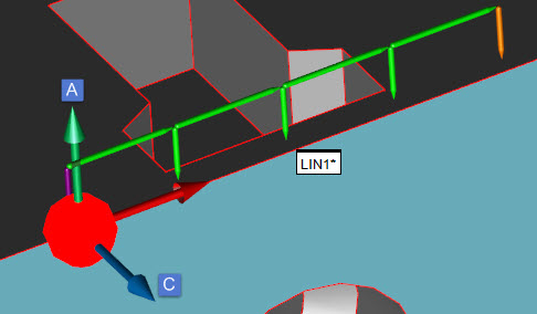
This sample bounded Auto Line shows the start and end points

This sample bounded Auto Line shows the start and end points (1) and (2), an Edge Vector of 0,-1,0 (A), a Line Vector of 1,0,0 (B), a Surface Vector of 0,0,1 (C), and a Pt. Size value of 4:
Modify any other options in the dialog box as needed.
Modify any items in the Contact Path Properties tab of the Probe Toolbox as needed.
For example, you might want to change the Hits value and the Depth value:

Auto Line with five hits now and a depth of 3 mm
Or, you might want the line to be measured along the other surface by modifying the Edge Vector:
Auto Line with a modified Edge Vector of 0,0,1 (A), a modified Surface Vector of 0,-1,-0 (C), and a depth of 1 mm
If you need sample hits, modify items in the Contact Sample Hits Properties tab of the Probe Toolbox as needed.
For example, if you need to sample the surface material offset from the edge, you might have something like this:

This sample shows the Auto Line with an Edge Vector of 0,-1,0 (A), a Surface Vector of 0,0,1 (C), a depth of 1 mm, and 1 sample hit using an indent 2 of 19 mm (D)
Click Create. PC-DMIS generates the auto line.
Using Wireframe Data on the Screen
To generate a line on the screen using wireframe data:
Select Yes or No from the Bounded list.
Select two edges (wires) of the surface where the target points are (if bounded by a second point, otherwise just click once) by clicking on the desired wires with the left mouse button. These wires should be on the same surface.
PC-DMIS draws the start location and, if creating a bounded line, the end point location. It also draws the line and edge point vectors.
Verify that the correct wires have been selected.
Modify any other options in the dialog box and the Contact Path Properties tab of the Probe Toolbox as needed.
Click Create. PC-DMIS generates a line.
Using Wireframe Data with the CMM
To generate a line using wireframe data:
The first hit that is taken indicates the X, Y, Z nominal start point. A second hit (needed if you've selected Yes from the Bounded list) generates the end point for the line. After the second hit, PC-DMIS also displays the I, J, K line vector and the I, J, K edge vector.
Any additional hits are equally spaced along the line's length. The approach vector is also updated to reflect an average of all previous hits (does not include the most recent hit) for the vector point.
The displayed data can be accepted at any time after the second hit is taken.
You should select the Find Noms option in the Mode list for this measurement method. For more information on nominals, see the "Mode List" topic in the PC-DMIS Core documentation.
Without Using CAD Data
If the line is to be generated without the use of CAD data:
Select Yes or No from the Bounded list.
If you are creating a bounded line, take two hits. If you are creating an unbounded line, take one hit.
Alter any other items on the dialog box and the Contact Path Properties tab of the Probe Toolbox as needed.
Click Create.
Typing the Data
This method allows you to type the values needed to create an auto line.
To create a bounded line:
Select Yes from the Bounded list.
Type the number of hits in the Hits box.
Type the depth for the line in the Depth box on the Contact Properties tab of the Probe Toolbox.
Type the X, Y, Z values for the Start and End points.
Type the I, J, K vectors.
Fill out any other options as needed in the dialog box.
Click Create. PC-DMIS generates a line based on the values you keyed into the dialog box.
To create an unbounded line:
Select No from the Bounded list.
Type the number of hits in the Hits box.
Type the depth for the line in the Depth box on the Contact Properties tab of the Probe Toolbox.
Type the X, Y, Z values for the Start point.
Type the I, J, K vectors.
Type the length of the line in the Length box.
Fill out any other options as needed in the dialog box.
Click Create. PC-DMIS generates a line based on the values you keyed into the dialog box.