
Auto Surface Point button
The Surface Point auto option allows you to define a nominal point location as well as a nominal approach direction that the CMM uses to measure the point defined. PC-DMIS allows you to define the number of points to use to measure a plane around the nominal point location, as well as the size of the plane. Once PC-DMIS measures the plane, it uses the calculated surface normal vector of the plane to approach the nominal point location for measurement.
The allowable number of sample hits needed to measure a surface point is zero or three.
To access the Surface Point option, open the Auto Feature dialog box for a Surface Point (Insert | Feature | Auto | Point | Surface).
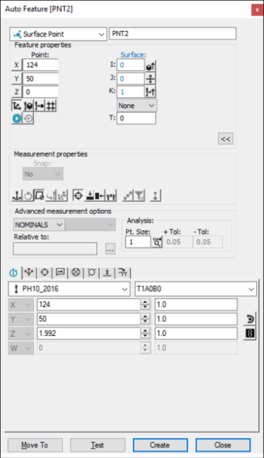
Auto Feature dialog box - Surface Point
With the dialog box open, use one of the following methods to create the feature.
Using Surface Data on the Screen
To use surface data to generate a surface point:
From the Graphic Modes
toolbar, click the Surface Mode icon ( ).
).
Position the mouse pointer in the Graphic Display window to indicate the desired location of the point (on the surface).
Click the left mouse button. PC-DMIS highlights the selected surface.
Verify that you have selected the correct surface.
PC-DMIS pierces the highlighted surface and displays the location
and vector of the selected point. The direction of the surface normal
vector is determined by the side of the part that is accessible to
the probe. If both sides of the part are equally accessible, PC-DMIS
uses the normal from the CAD data. The Flip Vector
icon ( ) on the dialog box lets you change the direction
of the approach.
) on the dialog box lets you change the direction
of the approach.
Click Create to insert the feature in to the measurement routine. If PC-DMIS detects additional mouse clicks before you select the Create button, it overwrites the previous information with the new data.
Using Surface Data with the CMM
To use surface data with the CMM to generate a surface point, touch on the desired surface of the part using the probe. PC-DMIS pierces the CAD surface closest to where the probe touched.
If the touch point is actually near the surface data, and the measured check box is not selected, the point feature is created and added to the Edit window immediately.
If the touch point is near the surface data, but the measure box is checked, the surface data is still used, but the feature is not created until you click the Create button.
If the touch point is not near the surface data, PC-DMIS treats the touch as an actual hit and displays the hit location and approach vector.
If you take a second hit prior to clicking the Create button, PC-DMIS uses the location data of the second hit.
If you take a third hit, PC-DMIS uses the three hits to determine an approach vector. The last hit is used for the location.
If you take more than three hits, PC-DMIS uses all but the last hit to determine the approach vector. PC-DMIS always uses the last hit to determine the location.
Using Wireframe Data on the Screen
To use a wireframe CAD data to generate a surface point:
Select two edges (wires) of the surface where the target point is by clicking on the desired wires with the left mouse button. (These wires should be on the same surface.) PC-DMIS highlights the selected wires.
Verify that you have selected the correct wires. A message box appears.
Select the target point on the created surface. This final selection is projected onto the plane that is formed by the two wire vectors and the first wire's height.
Using Wireframe Data with the CMM
If the surface point is to be generated using wireframe CAD data:
The first hit that is taken indicates the X, Y, Z nominal. PC-DMIS also displays the I, J, K vector. This value indicates the opposite direction of the CMM approach vector (pointing away from the surface). You can accept this data, or you can follow the messages in the message box requesting additional hits. A second hit updates the hit location and approach vector using the most recent hit.
The third hit on the surface changes the displayed X, Y, Z nominal to the current hit location. PC-DMIS makes a plane out of the three hits to find the I, J, K approach vector.
Any additional hits update the location of the hit with the most current hit information. The approach vector is also updated to reflect an average of all previous hits (excluding the most recent hit) for the surface point.
You can accept the displayed data at any time after you take the first, second, or third hit. Even if the third hit was not accepted, PC-DMIS internally resets the system, causing the next hit (hit #4) to become the first hit in the series.
You should select the Find Noms option in the Mode list for this measurement method. For more information on nominals, see the "Mode List" topic in the PC-DMIS Core documentation.
Without Using CAD Data
To generate the surface point without the use of CAD data:
The first hit that is taken indicates the X, Y, Z nominal. PC-DMIS also displays the I, J, K vector. This value indicates the opposite direction of the CMM approach vector (pointing away from the surface). You can accept this data, or you can follow the messages in the message box requesting additional hits.
A second hit updates the hit location and approach vector using the most recent hit.
The third hit on the surface changes the displayed X, Y, Z nominal to the current hit location. PC-DMIS makes a plane out of the three hits to find the I, J, K approach vector.
Any additional hits update the location of the hit with the most current hit information. The approach vector also updates to reflect an average of all previous hits (does not include the most recent hit) for the surface point.
Typing the Data
This method enables you to type the desired X, Y, Z, I, J, K values for the surface point.
Type the desired X, Y, Z, I, J, K values for the feature into the dialog box.
Click Create to insert the feature into your measurement routine.