Once you have created a feature, you can calculate dimensions for your report. You can generate dimensions at any time while you learn a measurement routine, and you can tailor them to fit individual specifications. PC-DMIS displays the result of each dimension operation in the Edit window.
This step generates four different dimensions.
Circularity of circles 2 through 9
Perpendicularity of line 2 with line 3
Coaxiality of cylinder 1 with cylinder 2
Perpendicularity of cylinder 3 with cylinder 2
This tutorial use Feature Control Frame dimensions. Select Insert | Dimension and ensure that the Use Legacy Dimensions menu item is not selected. For information on how to create FCF dimensions, see the "Using Feature Control Frames" chapter in the PC-DMIS Core documentation.
Define Datums
Before you can define the dimensions, you need to define the datums:
First, click at the end of the Edit window.
Select Insert | Feature | Dimension | Datum Definition to open the Datum Definition dialog box.
From the Datum Definition dialog box, create these datums:
Datum A - LIN3
Datum B - CYL2
First Dimension
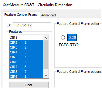
Next, create the first dimension, the circularity of circles 2 through 9:
Select Insert | Dimension | Circularity to open the XactMeasure GD&T dialog box.
From the Features list, choose CIR2, press Shift and choose CIR9.
In the Feature Control Frame editor, in the Feature Control Frame (FCF), click on the Feature Tolerance portion, and define a tolerance of 0.25.
Click Create and then Close. This inserts a dimension of FCFCIRTY1 into the Edit window.
Second Dimensions
Next, create the second dimension, the perpendicularity of line 2 with line 3 (datum A):
Select Insert | Dimension | Perpendicularity to open the XactMeasure GD&T dialog box.
From the Features list, choose LIN2.
In the Feature Control Frame editor, in the FCF, click on the Feature Tolerance portion, and define a tolerance of 0.25.
Set the primary datum to A.
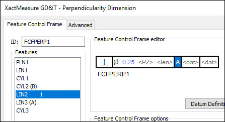
Click Create and then Close.
Third Dimension
Next, create the third dimension, the coaxiality of cylinder 1 with cylinder 2 (datum B):
Select Insert | Dimension | Coaxiliaty to open the XactMeasure GD&T dialog box.
From the Features list, choose CYL1.
In the Feature Control Frame editor, in the FCF, click on the Feature Tolerance portion, and define a tolerance of 0.25.
Set the primary datum to B.
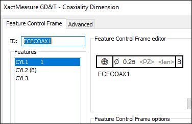
Click Create and then Close.
Fourth Dimension
Finally, create the fourth dimension, the perpendicularity of cylinder 3 with cylinder 2 (datum B):
Select Insert | Dimension | Perpendicularity to open the XactMeasure GD&T dialog box.
From the Features list, choose CYL3.
In the Feature Control Frame editor, in the FCF, click on the Feature Tolerance portion, and define a tolerance of 0.25.
Set the primary datum to B.
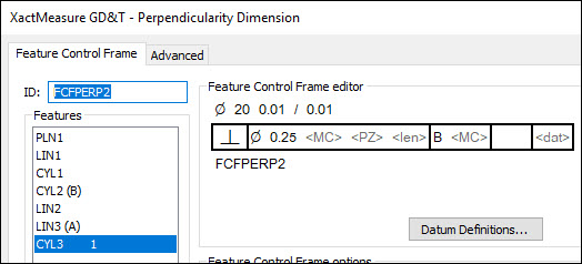
Click Create and then Close.
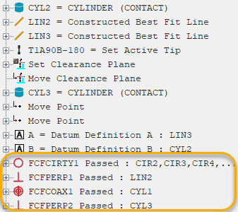
Your measurement routine should have these datum definition and dimension commands:
Go to the next step: "Mark Items to Execute"