Select the File | Import | IGES menu option. The Import dialog box appears.
Use the Import dialog box to navigate to the folder that contains the file to import. Then select the file.
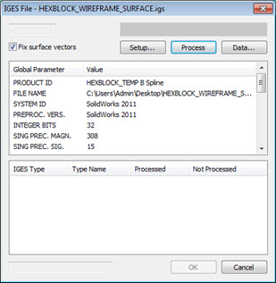
Click the Import button. PC-DMIS displays the IGES File dialog box. The IGES File dialog box displays all of the pertinent information about the indicated data file.
IGES File dialog box
If you want your surface vectors to be correct and always point away from the surface, select the Fix surface vectors check box. This is helpful for point cloud and laser scanning operations, but it does increase the import processing time. If you don't use laser scanning, you can clear this check box.
If you want to determine the CAD data that PC-DMIS processes and displays, click the Setup button (for information, see "Altering Display of Imported IGES CAD").
To view specific IGES feature data, click the Data button (for information, see "Using the IGES Data Dialog Box").
To attach this file to the selected measurement routine, click the Process command button. PC-DMIS indicates when the file is 100% processed.

IGES File dialog box after a file is processed
To complete the action, click the OK button. PC-DMIS displays the imported IGES model. Select the Cancel button to terminate the entire operation and close the IGES File dialog box.
If you want to manipulate a 2D CAD drawing three-dimensionally, thereby creating desired 3D levels, you can use CAD-level functionality. If you do this, your original data should be defined in a single plane parallel to the Z (= 0) plane. For complete information on CAD levels, see the "Working with CAD Levels" topic in the "Editing the CAD Display" chapter.
For information regarding the different input file formats, see the "Working in Offline Mode" section.
More: