From the Edit menu, point to Graphic Display Window, and choose Lighting, Materials.

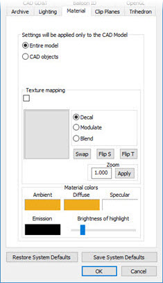
CAD and Graphic Setup dialog box - Material tab
The Material tab of the CAD and Graphic Setup dialog box consists of settings that you can apply to CAD objects making up the imported CAD part model or the entire part model altogether.
The first area of this tab contains two option buttons that allow you to determine the "active selection", either Entire model or CAD objects.

Entire model – This option applies the settings to the entire CAD model.
CAD objects – This option applies the settings to specific selected CAD objects making up the entire model.
Texture mapping

The Texture mapping area defines the texture to be applied to the active selection. PC-DMIS automatically applies the texture image as often as necessary to cover the entire active selection.
The check box displays the current bitmap name once you select a bitmap file to use for the texture. This check box is always selected when the active selection is a CAD object.
The large gray square area under the check box displays the current texture.
To apply a texture to your part:
Click the gray square area to open the standard Open dialog box.
You can use the Open dialog box to navigate and select a valid bitmap file. A bitmap file must have a width and height of 2 to some power. For example 2 to the 5th power is 32 and 2 to the 4th power is 16. So if your bitmap is 32 X 16 pixels, it would be a valid bitmap. If you had something like 32 X 20, PC-DMIS would display an error message.
PC-DMIS displays a preview of the selected texture inside the gray square area.
Click Open to accept the texture.
To apply the check box to the active selection, click the Enable check box as needed.
The other items in the Texture Mapping area determine how PC-DMIS should apply the texture and surface colors:
Decal prevents any of the surface’s color from being emitted, so you can only see the texture’s color.
Modulate and Blend use OpenGL algorithms to determine the final display colors.
Zoom controls the "zoom" factor applied to the current texture. The values greater than 1.0 zoom into the texture, repeating the texture less often. The values less than 1.0 zoom out of the texture, repeating the texture more often. For example, a value of 2.0 makes the bitmap twice the size (repeat half as often), and a value of 0.5 makes the bitmap half the size (repeat twice as often).
The buttons Flip T, Flip S, and Swap determine the orientation of the texture. The texture is a two dimensional image, the orientation is described in terms of S and T. In the images below, a custom texture with an arrow drawn atop helps to visualize what happens:
The original texture looks like this, an arrow pointing to the right with the top half of the arrow red and the bottom half of the arrow green:

Click Swap on the original to switch the orientation so that S becomes T and T becomes S. This causes the arrow to point up but to also flip the bottom and top of the arrow:
 (Swap
example)
Click Flip S on the original to change the direction of S. This causes the arrow to point to the left:
 (Flip
S example)
Click Flip T on the original to change the direction of T. This causes the arrow to flip, making the bottom and top switch places:
 (Flip
T example)
You can click these buttons in different combinations to get a variety of orientations for your texture.
Click Apply to see any changes you made to texture orientations or other material colors.
Material colors

The Material colors area defines the color information to be applied to the entire CAD Model.
The Ambient, Diffuse, and Specular function similarly to those already explained in the Light Colors area of the Lighting tab. See "Lighting Tab".
Emission - Materials may have an emissive color, which simulates light originating from an object. In the OpenGL lighting model, the emissive color of a surface adds intensity to the object, but is unaffected by any light sources. Also, the emissive color does not introduce any additional light into the overall scene.
Brightness of highlight - This slider controls the intensity of the highlight when looking at a curved surface.
More:
Applying Textures to the Entire CAD Model