Step 9 - Review the Calibration Results
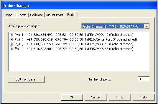
When the calibration of the FCR25 Probe Changer is complete, select the Ports tab in the Probe Changer dialog box (Edit | Preferences | Probe Changer). This tab displays the calibration information for the location of each calibrated port. For example:
Probe Changer dialog box - Ports tab with calibration results
When you view the results, look for the following. Any significant deviations from these expectations may be due to a bad hit.
The probe changer must be aligned parallel to either the X or the Y axis of the CMM.
The X and Y values should show equal spacing between ports (roughly 40 mm apart).
The Z values should be nearly identical, since the ports are all at the same height.
How a LOADPROBE command works with the probe changer:
During the execution of a measurement routine, the probe entities that you added to each port are automatically picked up from the port whenever PC-DMIS executes a LOADPROBE command for that probe.
Before it picks it up, the probe body moves to the mount point and then into the empty port to drop off the current probe.
The rack's keys rotate to the release position. The current probe remains in the port, while the probe body lifts away to detach.
The probe body moves over the load position above the port containing the probe.
The probe body moves down onto the new probe. The keys rotate again to automatically engage the new module.
The probe body moves back out of the port and over to the rack’s mount point.
The CMM continues to measure the part with the newly-loaded probe.