You must have an active Internet connection to see this video.

You can draw a box on top of a CAD image to automatically create multiple auto features for these supported feature types:
Auto Vector Point
Auto Surface Point
Auto Edge Point
Auto High Point
Auto Circle
Auto Cylinder
To Box-Select and Create Features
To use the box-select method to create multiple auto features of either the circle or cylinder auto feature types, follow this procedure:
Import the CAD model that has the auto features you want to box-select.
Rotate the part and select either wireframe or solid to select a view that best shows the features you want to include.
Access the Auto Feature dialog box (Insert | Feature | Auto) for either circle or cylinder auto features.
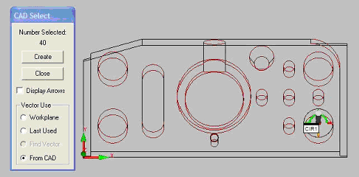
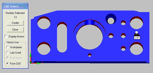
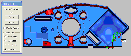
With the dialog box open, click the mouse, and drag a box around those feature types for which you want to create auto features. Release the mouse button. PC-DMIS displays the CAD Select dialog box, showing the number of objects selected.
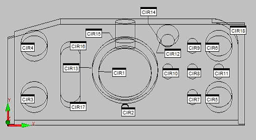
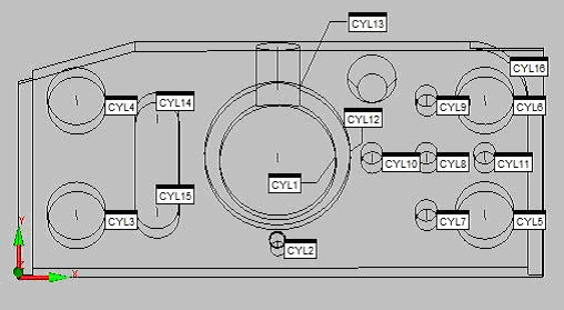
Click Create. Based on the objects selected, PC-DMIS generates multiple auto features of the selected type.
You must have an active Internet connection to see this video.
Box-Selecting Details
Box-selecting only works on objects visible in the Graphic Display window. This prevents unseen objects from being used in the creation of features.
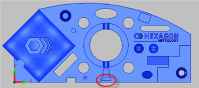
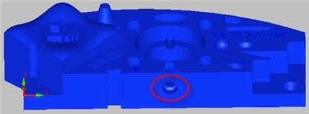
Models with little or no wireframe geometry should be slightly tilted (or rotated) in the Graphic Display window so that the desired surfaces and features are visible as shown below.
Example of a Slightly Rotated Part
Because of tessellation and display accuracy, the bleeding of underlying surfaces and curves may result in extra unexpected objects used to create the features. While PC-DMIS attempts to minimize this bleeding by comparing the selected objects with each other to determine the minimum number of pixels necessary to be considered a valid selection, this is not a foolproof method, and some mostly hidden objects may get selected in order to minimize the likelihood of eliminating a valid object.
When creating the features from the selected objects, objects with vectors perpendicular to the current view are mostly ignored. For example, using the Hexagon block displayed in Z+ with the entire model box-selected, PC-DMIS will not generate a feature for the front bore that intersects the center bore.
Selecting in the Z+ view, this circle's vector is perpendicular to the workplane and therefore PC-DMIS would not generate a circle for it.
If you tilted the part and then box-selected, PC-DMIS would select this feature.
PC-DMIS performs filtering routines to ensure that it doesn't use the same CAD object to create another feature in the same position.
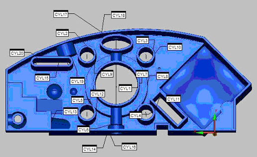
As PC-DMIS generates the features after you click Create, you can see each item's information displayed in the Status bar.
 Example
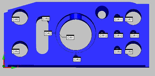
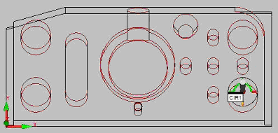
1: Box-Selecting Auto Circles with Wireframe Data
Example
1: Box-Selecting Auto Circles with Wireframe Data
Example
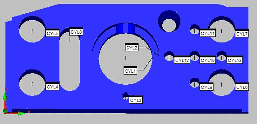
2: Box-Selecting Auto Cylinders with Wireframe Data
Example
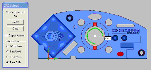
3: Box-Selecting Auto Circles or Cylinders with Surface Data
Example
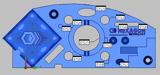
4: Box-Selecting Auto Cylinders with Both Wireframe and Surface Data
With point features, if the model has defined the points as CAD elements, you can box-select them with QuickFeatures. For more information, see "Creating QuickFeatures".
More: