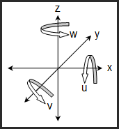
An alignment allows you to define your part's location and orientation in 3D space. It allows your measuring machine to know where the part is located. A part without any alignment has six degrees of freedom:
Three degrees of rotation (about the X, Y, and Z axes)
Three degrees of translation (origin in X, Y, and Z axes)

This diagram shows the six degrees of freedom in 3D space (x,y,z,u,v, and w)
Datum Reference Frame
A Datum Reference Frame (DRF) constrains the six degrees of freedom, fixing the part in 3D space.
A part alignment represents the DRF specified on the drawing. The primary, secondary, and tertiary datums define the DRF and identify the features to measure and use to create the alignment.
The three degrees of rotation are constrained by the I, J, K vector(s) of the datum feature(s).
The three degrees of translation are constrained by the X,Y,Z location(s) of the datum feature(s).
Constrains two degrees of rotation such that the leveled axis matches the vector of the selected feature.
This will always be the primary datum and must be a 3D feature with a vector.
Typical Features: Plane, Cylinder, Cone, or a constructed 3D feature.
Constrains one degree of rotation about the leveled axis such that the rotated axis matches the vector of the selected feature.
This will always be the secondary or tertiary datum and must be a 2D or 3D feature with a vector.
Typical Features: Plane, Line, Cylinder, Cone, or a constructed 2D/3D feature.
You can also select any two-point type features to simulate a line that can be used to rotate. These can be two points, two circles, two spheres, or a combination thereof. The direction of the simulated line is based on the order of the selected features.
Constrains three degrees of translation (origin) in X, Y, and Z-axis.
This sets the origin on primary, secondary, and tertiary datums or as per drawing requirements.
Typical Features: Any feature.
Alignment Tips:
LEVEL first, ROTATE second, and then set the ORIGIN for the X, Y, and Z axes. Never Rotate before Leveling!
Always LEVEL before measuring 2D features (lines and circles).
Always LEVEL and ROTATE before measuring points (measured point in X, Y or Z-axis)
There is no limit on the number of alignments saved in a measurement routine.
You can use the SAVE ALIGNMENT command to save an alignment to a file. This is typically done to create a fully automated measurement routine dependent on a holding fixture for the part.
Create a measurement routine that establishes an alignment on a fixture, and then save the alignment to a file.
Create a measurement routine, RECALL the alignment file at the beginning of the measurement routine and set it to run in DCC mode before measuring the first feature.
During measurement routine execution, the CMM pauses, prompts the operator to load part, then automatically measures the part (no manual alignment).
Right Hand Rule of Rotation - Point your right hand's thumb in the positive direction of the axis you are rotating about (+X, +Y, or +Z). The direction your hand naturally curls is the positive rotation about that axis. Negative rotation is the opposite direction.