If you load a measurement routine from 3.7 or earlier, PC-DMIS displays a message informing you that the way Angle dimensions were calculated has changed and that all Angle dimensions in the measurement routine were updated.
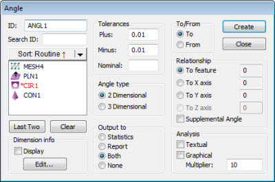
Dimension Angle dialog box
The Insert | Dimension | Angle menu option calculates the angle between a selected feature and either a second selected feature or a coordinate axis.
The measured value is an angle (blue). The Angle tolerance band is another angle (black).
For a 2D angle type, PC-DMIS projects the vectors onto the current workplane, and it calculates the angle from the first feature to the second feature or axis.
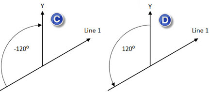
PC-DMIS gives a positive angle if it calculates the angle in a counter clock-wise direction. It gives a negative angle if it calculates the angle in a clock-wise direction.
The To and From options determine the direction of the calculation and the resulting sign (positive or negative):
If you select To, PC-DMIS calculates the angle from feature 1 to feature 2 (or selected axis).
If you select From, PC-DMIS calculates the angle to feature 1 from feature 2 (or selected axis).
By default, PC-DMIS uses the angle from feature 1 to feature 2 (or the selected axis). If you want the supplemental angle (180 degrees - angle), mark the Supplemental Angle box.

 Consider the following examples:
If you select one of these features (or feature types), PC-DMIS rotates the surface normal vector 90 degrees clockwise to represent a vector along the surface:
Plane
2D feature with width
3D feature with width
Consider the following examples:
More:
To Dimension the Angle Between Two Features: