Looking for XactMeasure GD&T dimensions? If so, see:

Dimension Symmetry dialog box
The Insert | Dimension | Symmetry menu option calculates the symmetry of a set of points with a datum feature, or two opposing lines with a datum feature.
If the first feature is a set, the second feature that is entered is the datum feature and must be either a plane or a line.
If the first feature is a line, the second feature must also be a line and the third feature that is entered is the datum feature. In this case the third feature must be a plane or a line. This dimension type is considered one sided, meaning a single positive value tolerance is applied.
If the third feature is a plane, the symmetry algorithm attempts to find a line on that plane that represents the datum. To find the correct line, it intersects (or crosses) the chosen plane with the workplane. For this reason, you should ensure that you are using the correct workplane.
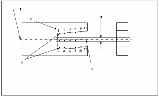
According to the geometric dimensioning and tolerancing standard, the following graphic indicates how a symmetry dimension is displayed and interpreted.

Symmetry Dimension

Symmetry Dimension - Interpretation
1 - The center plane of datum feature A.
2 - Order of point measurements.
3 - 0.8 wide tolerance zone.
4 - Opposed elements, with alternating points.
5 - Derived median points.
Explanation of Previous Graphic
Within the limits of size and RFS, all median points of opposed elements of the slot must lie between two parallel planes 0.8 apart, the two planes being equally disposed about datum plane A. The specified tolerance and the datum reference can only apply on an RFS basis.
Because of the way the symmetry is defined, PC-DMIS limits the features that can be used for the symmetry dimension. Since the points must be equally arranged about the datum in order to find midpoints between them, you must either select a feature set with alternating points or two opposing lines with the same number of points.
More: