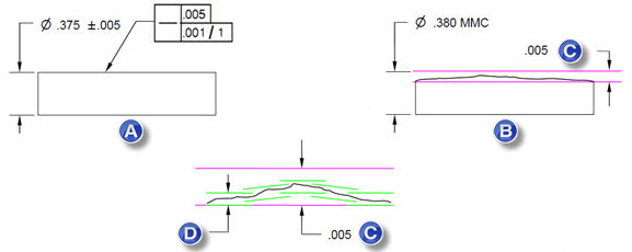
The Straightness form tolerance controls the shape of a 2D line element or a 3D axis without controlling orientation or location. Both use the same symbol, but the Feature Control Frame (FCF) is directed to the considered feature differently as shown below:
(A) Straightness of a Line. (B) Straightness of an axis.
Straightness of a line is a 2D specification that controls all line elements of a planar, cylindrical, or conical surface. The straightness tolerance is applied in the view where the controlled elements are represented by a straight line. Each line element must lie within a tolerance zone bounded by two parallel lines which are separated by the specified tolerance value. Material condition modifiers and datum features are not allowed.
(A) If your drawing has this. (B) It means this. (C) A .001 wide tolerance zone.
If you use a manual measuring device, such as a Romer arm, you cannot accurately measure straightness of a line element of a cylinder or cone. If you take measured data in different planar cross-sections, PC-DMIS interprets the nominal variation of the surface as form error.
Straightness of an axis is a 3D specification that controls the axis, or derived median line, of a cylinder. PC-DMIS automatically constructs a derived median line from the considered cylinder by calculating the center point of each circular cross-section. The derived median line must lie within a cylindrical tolerance zone with a diameter equal to the specified tolerance. Straightness of an axis allows material condition modifiers, but it does not allow datum features.
(A) If your drawing has this. (B) It means this. (C) virtual condition of .381. (D) A .001 diameter tolerance zone.
If you do not take the measured data in planar cross-sections, the software may not be able to construct the derived median line from the surface data.
When evaluating Straightness on a cylinder, you must take at least three levels of probe hits. The more levels of hits taken, the better the evaluation of the cylinder's straightness.
When you dimension a cylinder's Straightness at material condition, the Nominals tab in the XactMeasure GD&T dialog box displays a DF axis in the Position area to enable you to enter the size tolerance for the bonus calculation. See "Nominals Tab".
Sample Position area in the Nominals tab showing the DF axis
Straightness of a Line Per Unit Length
In addition to overall straightness, you can specify a straightness tolerance on a per unit length basis if you use the Per Unit check box. This creates a composite FCF, where two separate tolerances share the same straightness symbol. The upper segment on the FCF specifies the overall straightness tolerance. The lower segment on the FCF refines the overall straightness with a smaller tolerance value. The number that precedes the slash determines the tolerance. The number that follows the slash determines the length of the unit. This creates a straightness tolerance where the tolerance zone only applies over the specified unit length. The smaller tolerance zone floats within the entire length of the considered feature.
You can also use per unit length for the straightness of a cylinder's axis (not shown in this example).
(A) If your drawing has this. (B) It means this. (C) A .005 wide tolerance zone. (D) A .001 wide tolerance zone by 1 unit length. Each pair of green lines represents the individual unit lengths.
Straightness per unit length is calculated by dividing the line’s point data into subsets that each fall inside a length of the specified size. The straightness of each data subset is determined by calculating the minimum distance between two parallel planes that contain all of the measured points in the subset. The considered feature's point data must be dense enough to contain at least three points in each data subset. After the software calculates straightness for all unit lengths, the worst-case measured value is used. The considered feature passes the straightness tolerance per unit length if the worst-case measured value within the per unit tolerance value.
Considered Features: Measured Line, Measured Cylinder, Auto Line, Auto Cylinder, Constructed Line, and Constructed Cylinder.
From the Insert | Dimension menu, or from the Dimension toolbar, choose Straightness to display the XactMeasure GD&T dialog box.
From the Features area, select a line or cylinder feature that contains at least three data points (three cross sections).
From the Feature Control Frame editor area, define the tolerance value for the FCF.
If you want to refine your tolerance on a per unit basis, mark the Per Unit check box.
If you marked Per Unit, in the newly added line in the Feature Control Frame editor area, define the tolerance and size of the unit.
Click Create to calculate the straightness dimension.
Click Close to close the XactMeasure GD&T dialog box.
View the results by opening the Status window (View | Other Windows | Status Window) or the Report window (View | Report Window). If the cylindrical feature fails the cylindricity tolerance, PC-DMIS colors the text red.
The measured value is the minimum distance between two parallel lines that contain all of the points (hits) of the considered line. The straightness tolerance passes if the measured value is within the tolerance value.
The measured value is the minimum diameter of a cylinder that contains all of the points of the considered derived line. The straightness tolerance passes if the measured value is within the tolerance value plus the MMC/LMC size bonus.
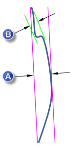
(A) The measured value for the upper segment is the minimum distance between two parallel lines that contain all the points (hits) of the considered line over the length of the line.
(B) The measured value for the lower segment is the minimum distance between two parallel lines of the per unit length. This is the worst deviation amongst all per unit segments.
Contact the Documentation Team
PC-DMIS 2019 R1
Copyright © 2019 Hexagon Manufacturing Intelligence – Metrology Software, Inc.
Help System last generated on 23 January 2019