 Updating
a Measurement Routine
from an Inspection Plan
Updating
a Measurement Routine
from an Inspection PlanWhile this documentation specifically addresses Inspection Plans, it also applies to updating measurement routine files created from Datalog files as well.
The Change Manager Plan updates a measurement routine you created from a previously-imported version of your plan with the latest version of your plan. The Change Manager CAD compares the features values of the measurement routine with those in the CAD. You can then update the measurement values based on the CAD values if necessary.
 Updating
a Measurement Routine
from an Inspection Plan
Updating
a Measurement Routine
from an Inspection Plan
Select the File | Change Manager | Plan menu item to open an Import dialog box.
You can import a .planxml or .xml file created from Planner or an .ip file created from the legacy Planner.
Choose the plan to import, and click Import to convert the file and show the Change Manager Plan dialog box:
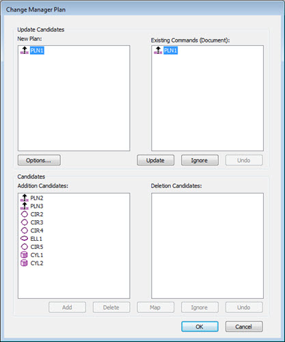
Change Manager Plan dialog box
You can double-click on a feature name from any list to show its parameters for that feature in order to compare values before updating your measurement routine.
Use the following controls to process the differences in the measurement routine and the imported plan.
Options - Opens the Change Managements Options dialog box. See "Change Management Options".
Update - This updates the selected feature into the Existing Commands from the New Plan. If you select a feature from one list, the software highlights the corresponding feature from the other list. You can select more than one feature at a time to update. This button also updates any associated dimensions.
Ignore - The selected feature is ignored for update into the Existing Commands from the New Plan when you click this option. Selecting a feature from one list will highlight the corresponding feature from the other list. You can select more than one feature at a time to ignore.
Undo (under Existing Commands area) - This is available only after you use Update or Ignore. This reverts the last change made.
Add - This adds the selected feature from the Addition Candidates list to the bottom of the existing plan. You can select more than one feature at a time to add.
Delete - The selected feature from the Deletion Candidates list is deleted from the existing plan when you click this option. You can select more than one feature at a time to delete.
Map - This is available only when you select one feature from both the Addition and Deletion Candidate lists. This replaces the selected Deletion Candidate feature with the selected Addition Candidate feature. This does not allow multiple selections. You can map both like and unlike feature types (for example, circle to a point or point to a point).
Ignore - This ignores (removes) the selected feature from the Deletion Candidates list, but it does not delete the feature from the existing plan when you click this option. You can select more than one feature at a time to ignore. Any feature that you remove from the list remains in the measurement routine.
Undo (under Deletion Candidates area) - This is available only after Add, Delete, or Map has been processed. This button reverts the last change made.
Updating
a Measurement Routine
from a CAD Model
Import a CAD model into your measurement routine (File | Import | CAD) or open a measurement routine that already contains a CAD model (File | Open).
Select the File | Change Manager | CAD menu item to open the Change Manager CAD dialog box:
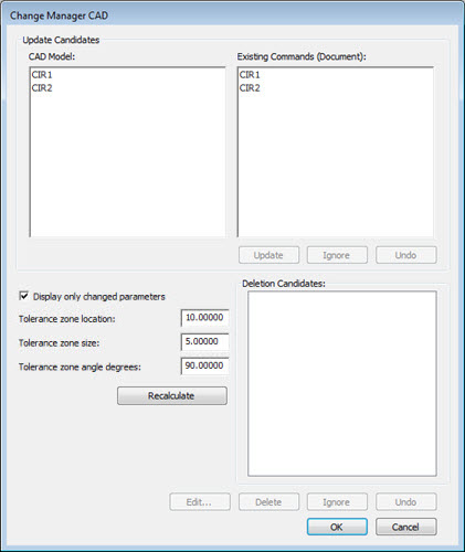
Change Manager CAD dialog box
If the software finds differences between the CAD and command feature component, it lists the features in the dialog box. It displays the CAD features in the CAD Model area and the measurement routine features in the Existing Commands (Document) area of the dialog box. Double-click any of the listed features to display its components.
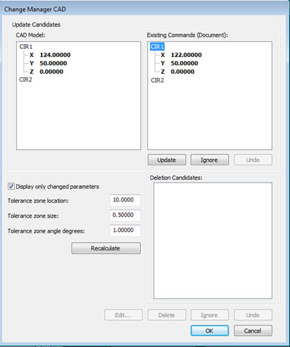
Change Manager CAD dialog box showing feature component values
Click the Update button to change the measurement routine's feature component values to those of the CAD's. This button also updates any associated dimensions.
The Change Manager CAD dialog box functions the same as the Change Manager Plan dialog box, except for the following items:
The Add button and the Additional Candidates section are not available.
The Edit button for the Deletion Candidates section displays the edit dialog box for the selected feature in the Deletion Candidates list so that you can edit the feature instead of just deleting or ignoring it.
Select the IPD file to apply to the imported Inspection Plan if you have not previously selected it. See "Legacy PC-DMIS Planner Parameters and Rules" for more information.
If the insertion point is not at the end of the measurement routine, the software prompts you to move the cursor to the end of the measurement routine before continuing.
Specify the Optimize Path options and click OK, or click Skip to ignore this step. See "Optimizing the Path" for more information. Review the optimization and close the Optimize Path Workflow dialog box.
Specify the options for "Inserting Clearance Moves Automatically" and click OK to complete this process, or click Cancel to skip this step.
If the tolerances have changed, click the Recalculate button to recalculate using the new tolerances. PC-DMIS then reviews the settings to determine which features are close enough to the CAD model to be considered the same.
The Change Management Options functions described for the Options button are integrated into the Change Manager CAD form.
Centering
and Highlighting Features
You can also use the Change Manager CAD dialog box to Center a feature or Highlight and UnHighlight features you need to change or delete. This can help you to better see where changes in a CAD model have been made or how you should update your measurement routine to match a new CAD model.
To access this functionality, from the Change Manager CAD dialog box (File | Change Manager | CAD), right-click on any feature name in any of the lists (CAD Model, Existing Commands or Deletion Candidates) to display the options.
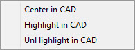
The options performs the following functions:
Center in CAD - This centers the selected feature location in the CAD Window.
Highlight in CAD - This highlights the selected feature in the CAD window. You can only highlight one feature at a time, and you cannot highlight any feature in the CAD Model list if the feature does not currently exist in the measurement routine.
UnHighlight in CAD - This clears the highlight on feature in the CAD window.
If the software doesn't automatically detect a modified CAD model and reload it in the Change Manager (which can happen if the original native CAD file is moved from its known location), you can use File | Change Manager | Reload CAD to manually tell the Change Manager to reload the CAD model.
PC-DMIS uses registry settings to determine the settings for the imported features. You can use the Measurement Strategy Editor or the Auto Feature dialog box to modify these settings.
More:
Contact the Documentation Team
PC-DMIS 2019 R1
Copyright © 2019 Hexagon Manufacturing Intelligence – Metrology Software, Inc.
Help System last generated on 23 January 2019