Laser Auto Features have a Horizontal and Vertical clipping zone. All scanned points within the clipping zone are initially evaluated.
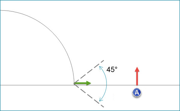
For 3D features (Surface Point, Plane, Cylinder, Cone, and Sphere), this setting compares the estimated normal of each scanned point to the feature theoretical normal or the vector of the CAD surface if a CAD model is used.
Points with a vector that fall outside of this angle are excluded when measuring the feature.
(A) - Plane (adjacent surface)
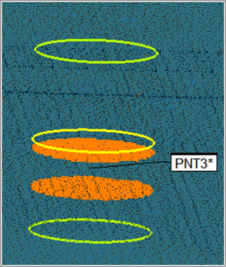
 Example
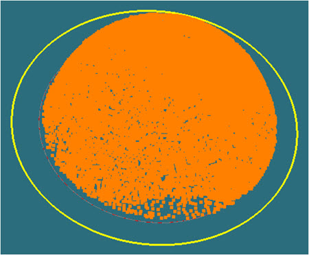
of the Max incidence angle applied to a 3D Laser
Auto Point feature
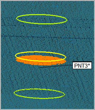
Example
of the Max incidence angle applied to a 3D Laser
Auto Point feature
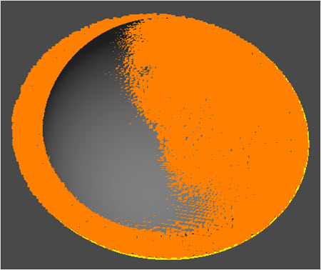
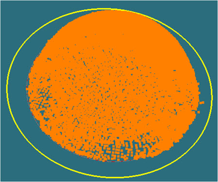
Example
of the Max incidence angle applied to a 3D Laser
Auto Sphere feature