PC-DMIS supports stacked rotary tables running on CNC machines. You can do the following:
Run a CNC machine with a machine model (see "Using a Machine Model").
Calibrate probe and rotary tables.
Properly animate and detect collisions with either the machine or part.
Use work offsets with a machine model (see "Using Work Offsets with a Machine Model").
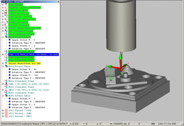
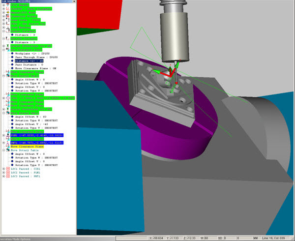
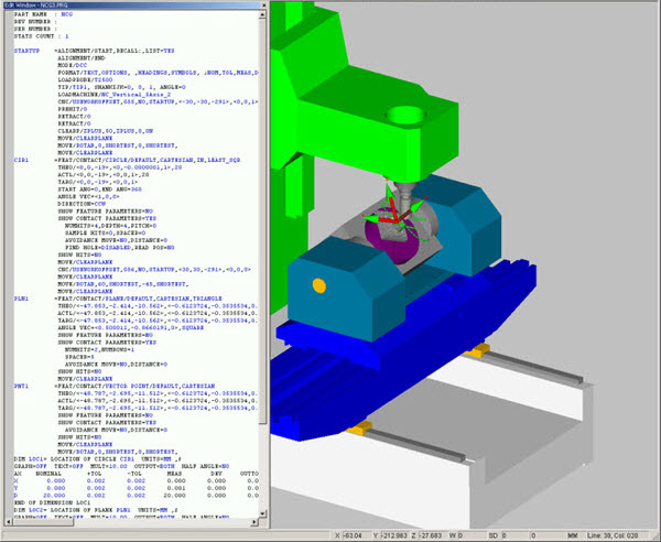
A simple PC-DMIS measurement routine (NCG3.PRG) using a stacked rotary table is shown below.
Stacked Rotary Table Measurement Routine
When animated, the probe moves about and there is no visual indication of the machine or rotary tables. Adding a machine model (NC_Vertical_5Axis_2) provides visual feedback, like this:
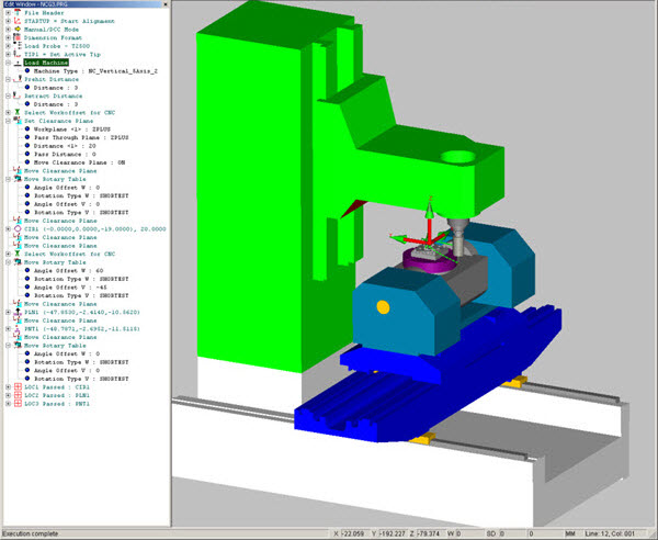
Stacked Rotary Table Measurement Routine with Machine Model
The rotary table setup is now automatically updated from the machine model. Select Edit | Preferences | Rotary Table Setup to view the updated values in the Rotary Table Setup dialog box:
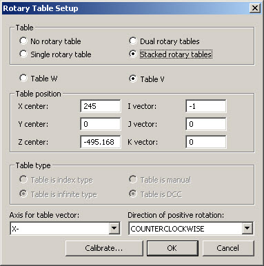
Rotary Table Setup Dialog Box for Stacked Rotary Tables
Adjusting the values manually in the dialog box now updates the machine model held in memory within PC-DMIS and used by the Path lines generator. The position of the part in some models can be automatically positioned at the center of the rotary table using the Auto Position button in the Setup Options dialog box. This is analogous to the other option of transforming the CAD.
Press the F5 key to display the Setup Options dialog box.
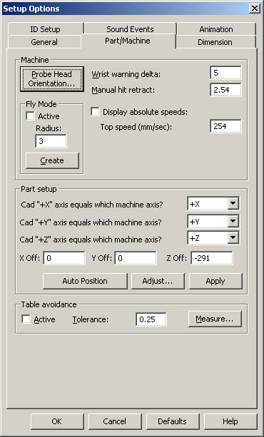
Setup Options Dialog Box for Stacked Rotary Tables
You can also see accurate Path lines after successfully calibrating the rotary table. PC-DMIS animates the machine moving the rotary tables more realistically.
Updated Stacked Rotary Table with Machine Model Measurement Routine
Collision Detection with part and machine is also possible.
Lowering the Clearance Plane and adding the Move Point (0,90,-50) is an example of a collision with the rotary table when it is rotated.
Non-zero prehit and retract distance are needed or collisions will be indicated for every hit.
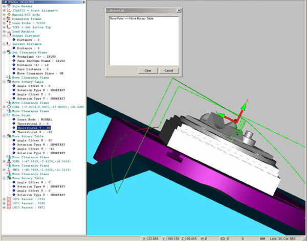
Updated Stacked Rotary Table with Machine Model Measurement Routine and Collision Detection
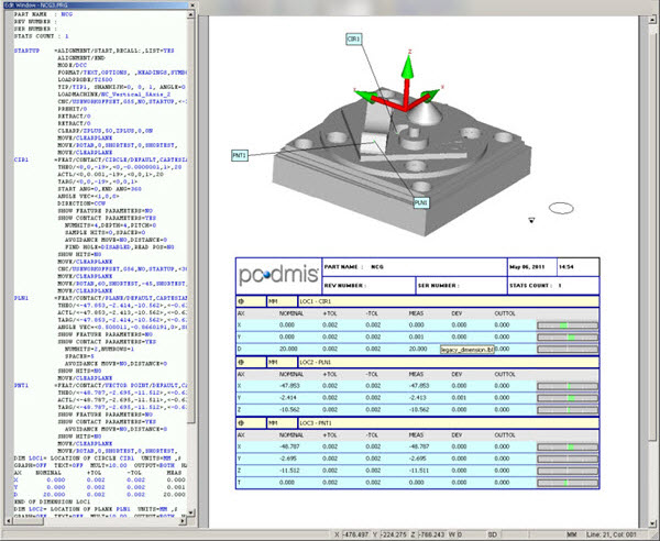
Creating a .cnc file produces the same Path lines as used when animating.
You can run the Journal file (HU801020110321172956.cnj) to produce a perfect report via the Execute function, then navigate and select the journal file when the dialog box appears. Click OK to generate the report.
When doing this test, the prehit and retract values should be zeroed prior to generating the .cnc file to avoid adding Overtravel distances to the Journal data.
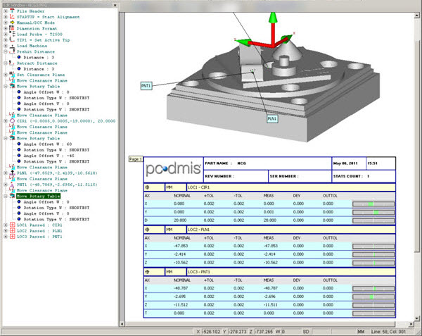
Stacked Rotary Table Measurement Routine with Report
Using Work Offsets with a Machine Model
The machine Work Offset needs to be specified by name and value by the user when working with a machine model if Animation and Collision Detection are to work correctly.
Multiple Work Offsets can be specified in this way. Scrolling up and down within the Edit window produces an effect that can be seen graphically, because the part moves whenever the work offset is updated in the same way as any update to a rotary table angle.
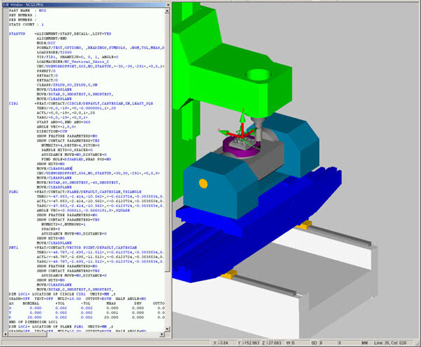
Stacked Rotary Table with Machine Model Measurement Routine and Work Offset initial line
Scrolling down one line, in this case to the Work Offset which is updated from G55 at (-30,-30,-290) to G56 at (30,30,-290), the CAD display shows the part moving (60,60) like this:

Stacked Rotary Table with Machine Model Measurement Routine and Work Offset down one line
Moving down two more lines and the rotary table angles are updated from (0,0) to (60,-45) and the display is updated, like this:
Stacked Rotary Table with Machine Model Measurement Routine and Work Offset down two more lines
Of course, when animating the measurement routine, these steps are also seen in sequence. When generating the .cnc measurement routine, the selected Work Offset is selected by name as usual. In this case, G55 is followed later by G56.
This can be tested by pasting the same point data from the generated .cnc file, into the .cnj Journal file and adding the lines for each work offset to generate a good report like the one shown below. When doing this test, the prehit and retract values should be zeroed prior to generating the .cnc file.
Stacked Rotary Table Measurement Routine with Report