 ). Otherwise, you can use AutoShutter to measure
using a manual machine.
). Otherwise, you can use AutoShutter to measure
using a manual machine.The top plane (Datum A) is used for the primary alignment datum. A reference plane is commonly not required in 2D vision measurements. However, in this example, the datum plane is measured to accommodate dimensioning flatness. This is useful in situations where you might have feature control frames that reference a datum plane.
Since the approximate location of the part is known, PC-DMIS can operate in DCC mode.
If you are using a DCC machine, from the Probe
Mode toolbar, select DCC Mode (). Otherwise, you can use AutoShutter to measure
using a manual machine.
To measure a plane features for Datum A:
Select the Magnification
tab  and adjust
the magnification so it is increased to the maximum setting (zoomed
in).
and adjust
the magnification so it is increased to the maximum setting (zoomed
in).
Select the Live View tab.
Position the camera over the part.
From the Illumination
tab  , adjust
the Top Light to a value that makes the
surface visible but not too bright. Move Z to focus as necessary.
, adjust
the Top Light to a value that makes the
surface visible but not too bright. Move Z to focus as necessary.
Select the CAD tab.
From the Graphic
Modes toolbar (View | Toolbars | Graphic
Modes), select Scale-To-Fit ( ).
).
From the Graphics
Modes toolbar, select the Surface Mode
button ( ).
).
From the Auto
Feature toolbar (View | Toolbars | Auto
Features), click Surface Point ( )
to open the Auto Feature dialog box for
Surface Point.
)
to open the Auto Feature dialog box for
Surface Point.
Click a point on the top surface.
Select the Hit
Targets tab  ,
and change the following parameters: Target Type = Automatic
Hit Target, Range = 5.0, Duration
= 5, and Find Surface Option = YES.
,
and change the following parameters: Target Type = Automatic
Hit Target, Range = 5.0, Duration
= 5, and Find Surface Option = YES.
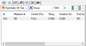
For each Automatic Hit Target, double-click the option below each property, and type the specified value.
Click Create to add this edge point to the measurement routine.
Click another point on the top surface, then click Create.
Repeat the step above (click a point, then Create) until a total of 8 points have been created (PNT2 - PNT9).
Click Close to exit the Auto Feature dialog box.