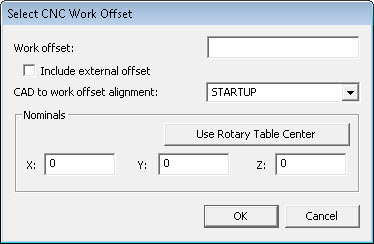
Using the Operation | CNC Programming | Use Work Offset menu option, set the work offset for the part you will measure into the NC controller.
Select CNC Work Offset dialog box
Make a note of its number. PC-DMIS NC supports standard work offset registers. (Example G54-G59 for Fanuc style controls). The objective is to match up the initial PC-DMIS NC alignment with a work offset.
In the case of Heidenhain Controls, modify the Preset Table or Datum Table.
Include External Work Offset
In the case of Fanuc Controls, this will include the value of G53 X, Y and Z as the total offset.
Case 1: The centers of the rotary tables are defined in machine coordinates, click the Include External Offset check box to enable it.
If G53 contains 100, 200, 300 mm and G54, 1P21 contains 1, 2, 3 mm, the total offset used to compute the location of the part in machine coordinates is 101, 202, 303 mm. This location would be used with the Rotary Table center definition in PC-DMIS NC to compute the location of the part when the table(s) are rotated.
Case 2: The center of the rotary table is put in G53, make sure the Include External Offset check box is unchecked. This is compatible with older versions of PC-DMIS NC.
This way of working puts the rotary table center at 0 (Zero). The standard work offsets (G54,G55, etc.) define an offset from this effective zero. The returned work offset for the part (using the numbers above) is 1, 2, 3 mm.