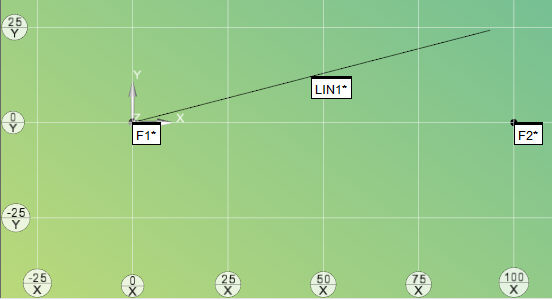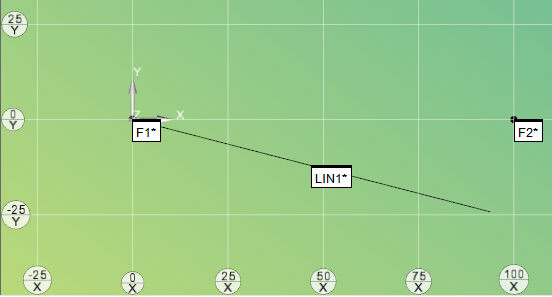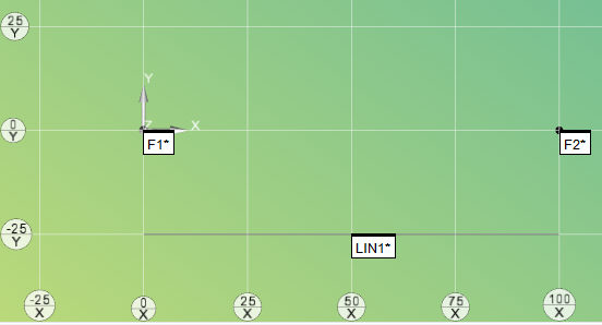
You can construct an offset line between the input features and then offset by specified distances from the input features.
To construct an offset line:
Access the Construct Line dialog box (Insert | Feature | Constructed | Line).
Select the Offset option.
Select at least two features from which to create the offset line. They can be of any type.
Click the Offsets button. The Line Offsets dialog box appears.
Line Offsets dialog box
Choose either to calculate the nominals from the offsets or calculate the offset value from the specified nominal values.
To calculate the nominals from the offset values, select the Calculate nominals option. In the Offset field, type the offset values for the desired features and then click Calculate.
To calculate the offsets, select the Calculate offsets option, modify the nominal values, and then click Calculate. For more information, see the procedures below.
Click the OK button to close the Line Offsets dialog box.
Click the Create button to create the constructed offset line based on your values.
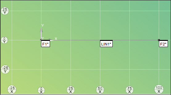
If the offset values exceed the distance between the input features, PC-DMIS cannot solve the offset line. Instead, it constructs a line without any offsets between the first and last feature.
The Edit window command line for this option would read:
CONSTR/LINE,OFFSET
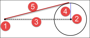
SURFACE NORMAL = i_vec, j_vec, k_vec, TOG1
ID = id1, id2, …
OFFSET = val1, val2, …
TOG1 = changes between MULTI POINT and TWO POINT. For new constructions, you should use MULTI POINT.
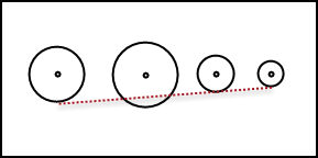
MULTI POINT - This newer algorithm is the default algorithm used whenever you construct a new offset line. It constructs the offset line between the selected input features. You can specify offset values from any of the features.
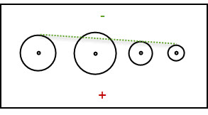
TWO POINT - This older algorithm is retained to support measurement routines from old PC-DMIS versions. It constructs the offset line between two input features. The offset value for the first feature must always be zero. Also, the way the positive or negative signs function is opposite how it works for MULTI POINT.
More:
Changing Offsets Directly to Calculate Nominals
Example of Calculating Nominals

 How
It Works
How
It Works