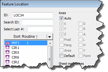
When the Auto check box in the Axes area in the Feature Location dialog box (Insert | Dimension | Location) is checked, the axes that appear in the dimension are selected according to the default axes of the feature type, but they are unavailable:
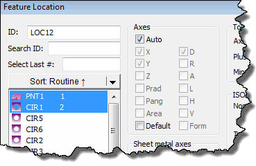
If you select multiple features of different types (for example a circle feature and a point feature), the Axes area selects the axes to use for the last-selected feature:
In some circumstances, it may be necessary to override the default setting. The Default check box remains available so that you can alter the format of the default output.
To alter the default output:
Select each feature to dimension.
Select the Default check box. The Auto check box clears, and all axes become available for selection.
Select the appropriate axes as needed.
X
= Prints the X axis value.
Y = Prints the Y axis value.
Z = Prints the Z axis value.
Prad = Prints the Polar Radius.
Pang = Prints the Polar Angle.
Area = Prints the area of a selected Blob
feature. It appears as AR in the report and in the Edit window in Command
mode.
D = Prints the Diameter value. For an ellipse,
this is the minor diameter value (same as H).
R = Prints the Radius (half of the Diameter)
value.
A = Prints the Angle value.
L = Prints the Length (used for cylinder, cones,
slots, and ellipses.) For an ellipse, L gives you the major diameter value.
H = Prints the Height (used on cones, cylinders,
and ellipses). For an ellipse, H gives you the minor diameter value.
V = Prints the Vector location.
Form = Prints the feature's integrated form dimension
with the location dimension.
For a circle, cylinder, or cone feature, this is the Roundness (RN) dimension.
For a plane feature, this is the Flatness (FL) dimension.
For a line feature, this is the Straightness (ST) dimension.
Click the Create button.
Once the output values have been changed to something other than the default, PC-DMIS uses the new settings for all subsequent dimensions. If you want PC-DMIS to then use the original default axes, you must reset the format to the default settings.
To reset the format to the default settings:
Select the Default check box.
Select the Auto check box. All of the axes check boxes become unavailable.
Select each feature to dimension. The original default axes are selected.
Click the Create button.
PC-DMIS automatically resets the dimension to print the default axes according to the feature type.