Select Insert | Dimension | Datum Definition.
From the GD&T XactMeasure
dialog box, click the Feature Control Frame
tab. Then at the datum compartment of the FCF click the plus button
( )
.
)
.
A datum is a theoretically-perfect plane, point, or axis reference feature that represents the mating part. Datums are referenced in Feature Control Frames (FCFs) to constrain up to six degrees of freedom (three degrees of translation and three degrees of rotation). To define the datums used in FCFs, you should first create the features that will become the datums. These features can come from auto features, measured features, or constructed features. Once you create the features, use Datum Definition (DATDEF) commands to define them as datums. Each DATDEF command associates a datum letter (for example, datum A) with a feature in your measurement routine.
Creating a Datum Definition
To define a datum, use the Datum Definition dialog box. You can access this dialog box in these ways:
Select Insert | Dimension | Datum Definition.
From the GD&T XactMeasure
dialog box, click the Feature Control Frame
tab. Then at the datum compartment of the FCF click the plus button
()
.

PC-DMIS displays the Datum Definition dialog box.

Datum Definition dialog box
Datum - This box defines the datum ID.
 - The box under the Datum box filters the list to show only those
features that contain the typed characters.
- The box under the Datum box filters the list to show only those
features that contain the typed characters.
 -
This drop-down arrow to the right lets you define how to sort the
list of features.
-
This drop-down arrow to the right lets you define how to sort the
list of features.
The datum letter ("A" in the above screen capture) defaults to the next available datum letter. PC-DMIS labels datums from "A" to "Z" and then from "AA" to "ZZ". Select a feature to be associated with this datum letter from the List of Features, and click Create. The Create button becomes activated whenever you select a feature from the list. When you create a definition, PC-DMIS inserts a DATDEF command into the Edit window. For example, if you had selected PLN1 and associated it with the letter "A", the Edit window command would read:
DATDEF/FEATURE=PLN1,DATUM=A
The feature you selected appears in the list of features with the associated datum letter in parentheses. From the above PLN1 example, it would now appear in the list as PLN1(A).
To create additional DATDEF commands, continue to select features, and click Create. If you don't want to create your datums in the default alphabetical sequence, you can modify the letter in the Datum box before you click Create.
Once you have created all your datums using the Datum Definition dialog box, you can then use the XactMeasure GD&T dialog box to create FCF dimensions and assign your defined datum features to those dimensions.
Bonus Refinement
When calculating the bonus on a datum, if there is a previous Position dimension or orientation dimension on that datum feature, then the Position and/or orientation tolerance is added to the datum bonus to calculate the virtual size of the datum.
Specifying Compound Datums in the FCF
A drawing's callout shows a compound datum using the format A-B (where the datums are labeled A and B). This indicates that the specified datums should be used together as if they were a single datum.
Compound datums only function with a Position FCF dimension or Profile FCF dimension. You can only choose circle or cylinder features (planes are not supported as compound datums).
To specify compound datums:
Create the individual datums. See "Defining Datums" for information on how to do this.
Select the menu item or toolbar icon to create a Position or Profile FCF. The XactMeasure GD&T dialog box appears.
Specify the compound datum in the <dat> field of the Feature Control Frame Editor area. While the list only shows individual datums, you can type the required datum combination directly. Do this by selecting or typing the first datum's ID, a dash, and then the ID for the last datum in the combination. If your compound datum used datums A and B, it would look like this:
Select the feature (or features) for your FCF.
Fill out anything else needed for your FCF.
Click Create.
How Bonuses are Applied for Compound Datums at MMB
Suppose you define a Position FCF for a hole using a compound datum D-E at MMB like this:
Datum A is a surface.
Datum D is a hole.
Datum E is a another hole.
PC-DMIS calculates the bonus for each of the datums in the compound datum based on the measured size of each datum, as well as the plus and minus tolerances for the D2 axis (secondary datum) as specified on the Nominals tab:
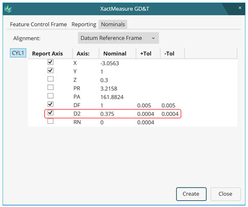
Nominals tab showing D2 Axis with +Tol and -Tol Values
The bonus for datum D may be different than the bonus for datum E based on the measured sizes of the two holes. The fitting process takes this into consideration.