
This topic displays notes and other information about the Position Feature Control Frame (FCF) dimension.
Rules on Position FCF
Position rules are documented in the "Rules for Using Feature Control Frame Dimensions".
Size Symbol
When choosing circular features to dimension (circles,
cylinders, or spheres), you can determine the type of size symbol used
on the line that defines the size tolerances for the FCF. By default,
the diameter symbol is used:
However, if you want to dimension a feature's size based off its radius instead of its diameter, you can instead choose the radius symbol: R
When you click Create, PC-DMIS creates the dimension and calculates the feature's nominal size value and any tolerance values based on the type of symbol in the selected dimension:
If you chose the diameter symbol, PC-DMIS uses the nominal diameter of the feature.
If you chose the radius symbol, PC-DMIS uses one half the nominal diameter of the feature. The tolerance values are the radius tolerances (one half of the diameter tolerances).
For example, the following images show the exact same four circle features dimensioned using the same nominal size and tolerance values, but with different calculations due to the size symbol selected:
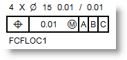
Using Diameter for size
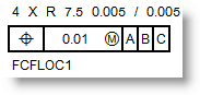
Using Radius for size
These values are then used in other areas of PC-DMIS, such as the Edit window and the Report window.
Specifying a Projected Tolerance Zone for Position

Sometimes you need to project the tolerance zone beyond the boundaries of the feature. This is typically used with mating parts. You can define a projected tolerance zone for the Position FCF by selecting the projection zone symbol (the letter P within a circle) from the <PZ> compartment. In the <len> compartment, you need to type the height of the projected zone beyond the feature of size. The height value needs to match the maximum height of the mating feature.
Reporting the Local Maximum and Minimum Size
You can report the local maximum and minimum size of an Auto Cylinder feature.
To do this:
From the Features list, select an Auto Cylinder feature.
From the Feature Control
Frame editor area, choose the Position symbol  .
.
From the Feature Control Frame options area, from the GD&T standard list, choose ISO 1101 to display the Local Size list.
From the Local Size list, choose Local: Max & Min.
Click Create.
When you generate your report, the local maximum and minimum size of the Auto Cylinder feature appear as two rows: LOCAL MAX and LOCAL MIN, as shown in this example:
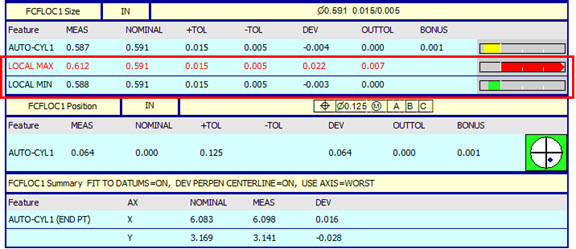
Position Reporting Format
PC-DMIS reports the following in the Report window:
The deviation of each feature in a set and not just the deviation of the entire set. This helps you better determine which feature is out of tolerance in a pattern of features.
The shifted position of the datum as a result of the datum fitting (with datums of size).
The total datum shift in X, Y, Z and rotation in U, V, W done by the fitting algorithm.
When reporting a Position FCF, a lot of information is available. To avoid confusion and see how the FCF affects the calculations, PC-DMIS splits this information into four parts:
Size information. This gets evaluated separately from the position of the feature.
Bonus tolerance information of the main feature or set
Datum information including the datum shift and datum rotation
Feature or set position information.
The additional information is very useful. For example, the datum shift information can be a big factor for an out of tolerance Position dimension. You can tell whether the feature or datum is in the wrong place.
See "Feature Control Frame Reporting Tables for some visual examples.