
Feature Based Clipping area for non-plane auto features
PC-DMIS can clip laser data in both the horizontal and vertical directions when you type a distance in the Horizontal box and, when available, the Vertical box. This distance clips all of the laser data outside of the defined distance and excludes that data when it extracts the feature.
Alternately, for the Plane auto feature, you can clip data within an offset boundary around all of the CAD elements on a surface. This is also termed CAD segregation. See "CAD Offset" below.
For the Cone auto feature, the value for the Horizontal option defines how much larger than the theoretical diameter is the circular boundary within which the feature points lie. The value for the Vertical option defines how much longer than the theoretical length is the cylindrical boundary within which the feature points lie.
Horizontal and Vertical Clipping
All of the auto features support horizontal clipping. These features support vertical clipping:
Circle
Cone
Cylinder
Polygon
Edge Point
Round Slot
Square Slot
Surface Point
Plane
The clipping distances defined in the feature based clipping rings are shown as colored rings. The horizontal clipping appears as a yellow ring, and the vertical clipping appears as a light green ring.
 and vertical clipping ring")
Sample Circle auto feature with horizontal clipping (A) and vertical clipping ring (B)

Sample Plane auto feature with horizontal and vertical clipping enabled

Feature Based Clipping area for Plane auto feature
The CAD offset check box is available for all 3D Auto features (Plane, Cone, Cylinder and Sphere).
You can enable the CAD offset option for Plane, Cone, Cylinder and Sphere auto features. The CAD offset option provides a way for PC-DMIS to shrink away from the selected CAD face and eliminate points which are within the offset distance to the edges of the feature.
For Plane auto features, when you select this check box, PC-DMIS creates a yellow offset boundary around each feature in the CAD model on the surface. For a Cone, Cylinder or Sphere auto feature, PC-DMIS does not display this yellow offset boundary outline.

Example of a Plane auto feature with CAD-based clipping enabled
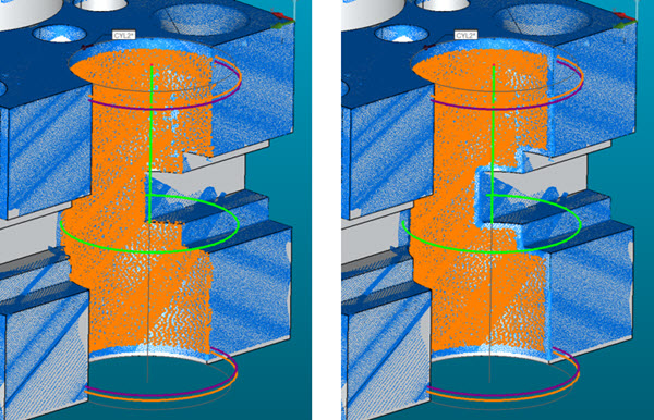
Example of a Cylinder auto feature with no CAD offset (left) and with 2mm CAD offset (right)
You must select a CAD face when using the CAD offset option.
PC-DMIS clips the laser data that falls inside of an offset boundary for all of the features in the CAD model on a surface. The data outside of the offset boundary is used to solve the plane.
For example, consider the image below, which shows a section of a sample part. The translucent orange overlay, added to the image here for clarification only, indicates the data that PC-DMIS would use to create the Plane auto feature:
