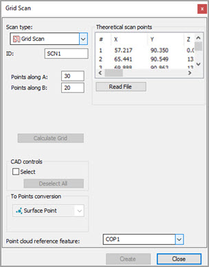
Grid Scan dialog box
The Grid Scan method creates a grid of points within a visible rectangle and then projects those points down on top of any selected surfaces. The rectangle and, consequently, the grid of points, depend on the orientation of the CAD model in the CAD tab.
Use the Hits along A and Hits along B boxes to define how many hits inside the boundary will get spaced and dropped onto the selected surface or surfaces.
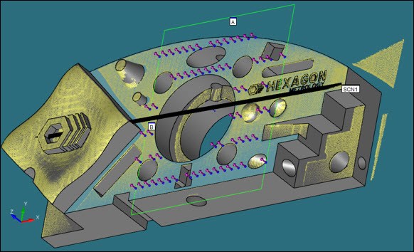
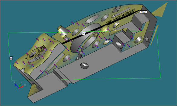
Consider the following figures that show grid Surface Points extracted from a COP:
Creating a Grid Scan
Ensure that you have a Laser probe enabled.
Place your CAD model into Solid mode.
Place PC-DMIS into DCC mode.
Select the Insert | Scan | Grid menu item. The Scan dialog box appears with the Grid Scan already selected in the Scan type list.
If you want to use a custom name for the grid, type the name of the grid in the ID box.
In the Hits along A and Hits along B boxes, specify how many hits in the A and B directions will get spaced and dropped onto the selected surface or surfaces.
Click and drag a rectangle on the screen over the surface or surfaces you want to include in your scan. This rectangle defines the boundary of the grid, which will be projected onto the CAD surface or surfaces. PC-DMIS draws points on the CAD model on any surfaces that were selected when you drew the rectangle.
Mark the Select check box if you want to deselect some surfaces. PC-DMIS highlights the selected surfaces and draws points only on them. It does not draw points on any deselected surfaces, even if they are included in the boundary of the rectangle.
If you mistakenly select a surface, press Ctrl and click on that surface a second time to deselect it. To deselect all of the highlighted surfaces at once, click the Deselect All button.
To recompute grid points (that is, to apply different A and B values on the selected surfaces), select the Calculate Grid button at any time.
In the Point cloud reference feature box, type the ID of the COP object from which to extract the surface data.
In the Hit Type list, Surface Point is the only option available since the scope of dialog box is to convert grid data into Surface Point laser commands. PC-DMIS inserts these commands into the Edit window when you click the Create button.
Click the Create button. PC-DMIS inserts the Surface Point laser commands into the Edit window in a collapsed Group command.