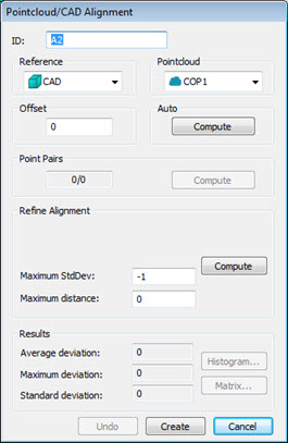
Default view of Pointcloud/CAD Alignment dialog box
The Pointcloud/CAD Alignment dialog box contains these options:
ID - This displays the identification label for the alignment.
Reference - Select the point of reference for your alignment, usually either from the CAD itself or a defined COP.
Pointcloud - This list lets you choose the cloud of points to use in the alignment.
Offset - This defines an offset value for a surface CAD model and is typically used with sheet metal parts. Applying an offset value essentially gives the surface CAD model a thickness so you can align the pointcloud data to a different face that isn't represented in the surface CAD model. For example, if you have a surface CAD model for the top of a part but you want to align to a corresponding bottom surface, you could apply an offset value of the part's thickness to align the scanned data to the bottom side. Use a positive value if you want to apply a thickness in the same direction as the surface normal vector; use a negative value if you want to apply a thickness opposite the surface normal. This option is available for Pointcloud to CAD alignments.
Auto - This area lets you automatically align the CAD with the cloud of points by using the Compute button. This option is available for Pointcloud to CAD alignments.
Point Pairs - This area lets you create a rough alignment based on selected points from the CAD that correspond to selected points from the pointcloud. Once you have the needed pairs selected, you can use the Compute button to perform the rough alignment.
Refine Alignment - This area allows for a more refined alignment. Only the Maximum Distance option is available for Pointcloud to Pointcloud alignments.
Depending on the alignment being made, the Refine Alignment area of the dialog box may consist of the following items:
The first two options (Total points and Maximum iterations) are only available if PC-DMIS IS NOT set up to use the Reshaper SDK for alignment computations. For details on using the SDK for alignment computations, see the topic "UseSDKForCopCadAlignments" in the PC-DMIS Settings Editor documentation.
Total points - This box defines the number of random sampled points used to refine the alignment. This number must be a value of at least 3. A good number is around 200 points.
Maximum iterations - This box defines the number of repetitions the process will make in order to refine the alignment.
Compute - This button begins the refined alignment process. A progress bar on the status bar shows the progress as the process moves through the alignment iterations.
Maximum StdDev - Maximum StdDev is the maximum standard deviation used during the execution of an auto alignment. If the entered value is exceeded during the command execution, you are prompted to optionally pick point pairs on the CAD/Pointcloud. A value of -1 disables the Maximum StdDev functionality.
Maximum Distance - Defines the maximum distance PC-DMIS looks from the CAD for valid COP points. If no value is entered, the default value of 0 (zero) is used and the maximum distance becomes half the distance of the CAD bounding box.
Results - This area contains the following items:
Information boxes showing the Average Deviation, Maximum Deviation, and Standard Deviations of the cloud of points in relation to the CAD model.
Histogram - This button takes a random sample of points from the pointcloud, projects them onto the CAD, and then shows the deviations for that sample in the Pointcloud Alignment Histogram dialog box.
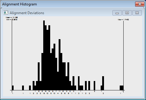
Sample Pointcloud Alignment Histogram dialog box
Matrix - This button displays the Alignment Matrices dialog box for the pointcloud alignment. The numerical values of the alignment: the offset and the rotation matrix are listed.
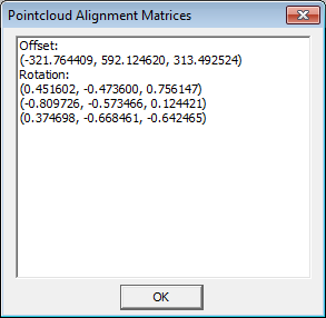
Sample Alignment Matrices dialog box for the alignment