Move Feature dialog box
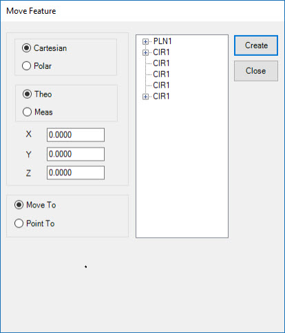
The Move Feature dialog box
is available when you use either a Leica Tracker or a Leica Total Station
device. It appears when you select the Move Feature
toolbar icon  from the Tracker Operation or Total
Station Operation toolbar. You can also select the Tracker
| Move Feature or Total Station | Move Feature
menu item.
from the Tracker Operation or Total
Station Operation toolbar. You can also select the Tracker
| Move Feature or Total Station | Move Feature
menu item.
The Move Feature dialog box contains the Move To and Point To options. These commands are used only with the Leica Total Station or Leica Tracker devices. In addition to the standard move ability of other DCC systems, the Point To command exploits the unique capabilities of these tracker-type systems by using the device as a laser pointer to identify, directly on the part, the location of out-of-tolerance points.
Move To
This option moves the device to a specific location where it then tries to find a reflector.
To move to a point, select the Move To option and then define where it should move to. There are three ways to specify the location to which it should move.
Method 1: Type the values into the X, Y, and Z boxes (or R, A, and Z if you use the Polar option).
Method 2: Select the feature that you are going to move to out of the Feature list. When you select the feature, PC-DMIS fills in the X, Y, and Z values based on the centroid of the feature.
Method 3: Expand the feature by selecting the + symbol next to it to display the hits on the feature. While "hits" is something of a misnomer, it means the point measured by the laser device. Select one of the hits from the list. PC-DMIS fills in the X, Y, and Z values for that hit.
To move to the measured or theoretical value for the point, choose either the Theo or Meas option.
Once you have set up the command correctly, click Create to insert the command into the Edit window.
MVF1 =MOVE FEATURE/MOVE TO,CARTESIAN,THEO,<-36.3574,33.3898,-10.8127>,
FILTER/NA,N WORST/1,
POINT TO METHOD/NA,DELAY IN SEC/0.0000,
REF/PNT1,
When PC-DMIS executes this command, the device automatically moves to the position indicated and attempts to find a reflector. If no reflector is found, an error displays that says "AUT_FineAdjust - Request timed out". To get past this error, if there is a nearby reflector, use the Execution Options dialog box and stop the execution, adjust the location to point nearer the reflector, and then click Continue. If a reflector is not close by, click Skip to move onto the next point.
Point To
To point to different hits, the procedure is the same as the "Move To" information above, but there are some additional options. With Point To you can also select from available dimensions in the measurement routine. If you select a dimension, PC-DMIS displays the Point To Filter and Point To Method areas. You do not need to select individual hits in the expanded dimension. All of the hits visible in the dimension will be pointed to, although you can use the Point to Filter area to filter hits.
Point To Filter

The Point To Filter area displays options that control which hits are pointed to. The options include:
All - PC-DMIS points to each point in the dimension.
Min/Max - PC-DMIS identifies and points to only the Min and Max points.
Out Of Tolerance - PC-DMIS points to only the out-of-tolerance points.
N Worst - PC-DMIS points to a number of "worst points". These points may or may not be in tolerance. This sorts the data based on the proximity to the theoretical values.
When you choose one of the options in the Point To Filter area, PC-DMIS updates the list of hits for the selected dimension in the dialog box to reflect the points to which PC-DMIS points the laser beam. For example, if you select Min/Max, the list of hits in the selected dimension updates with only two hits in the list, which represent the min and the max points for that dimension. If you choose All, the list updates and displays all of the input hits of that dimension.
Point To Method
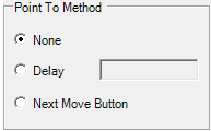
The Point To Method area lets you indicate how the device cycles through the list of points. The options include:
None - No delay or user input is needed to move to the next point. It points to each of the points without delay just as soon as the device can physically proceed to the next point.
Delay - This delays the cycle time by a specified number of seconds. When executed, the device points to the first point in the list, turns on the laser, and waits the specified amount of time. When the time expires, the laser turns off, and the device moves to the next point and repeats this process until all of the points in the list have been pointed to.
Next Move
Button - During execution, a Point To Execution
dialog box appears and shows the index of the point in the list and
its location.
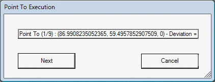
The dialog box has Next and Cancel
buttons, which allow the operator control over when to point to the
next hit in the list. The device moves to the first point, turns on
the laser, and then waits until the operator clicks Next.
It then moves to the next point in the list.
You can use the Edit window's Command mode to edit the command. Or, you can select the command in the Edit window and press F9 on the keyboard to edit the command.