Probe Toolbox - CWS Parameter tab
The CWS Parameter tab in the Probe Toolbox (View | Other Windows | Probe Toolbox) is available once the system has been appropriately configured:
The CWS has to be configured as the active laser system. Usually, this is done locally by the factory during the startup procedure or by a Service Engineer.
Once the system is correctly configured, you must define a probe with the correct properties. The probe is constructed through the Probe Utilities dialog box. You should use the OPTIV_FIXED selection and a lens that includes CWS. This should be defined in the USRPROBE.DAT file. This is also usually provided locally by the factory.
The CWS Parameter tab can include the following information:
Frequency (Measurement Rate)
The measurement rate sets the number of measured values the CWS records per unit time. For example, when the measurement rate is set at 2000 Hz, 2000 measurement values are taken per second. The intensity indicator on the display can help you select the correct setting. In the case of surfaces with very low reflectivity, it may be necessary to reduce the measurement rate. This has the effect of illuminating the optical sensor‘s CCD-line longer and thus making it possible to measure even if the reflected intensity is very low.
Exposure Time and Auto Intensity
Under Intensity, you can select the relative pulse duration of the LED, and with it the effective brightness of the light source. The Auto Intensity option is useful when the measurement surface changes in reflectiveness. If, for example, you are measuring a highly reflective surface, on which the highest measurement rate still results in over-modulation, then it makes sense to set Auto Intensity to No and set the Lamp Intensity option manually.
Another option would be to leave Auto Intensity set to Yes, and reduce the exposure time. If a poorly-reflecting surface is to be measured with a high measurement rate, this can be achieved by means of a longer pulse duration or longer exposure time.
Dark reference is absolutely necessary after every change to the exposure time. Please refer to the appropriate section of your CWS Unit Operators Manual.
Offset
Depending on the reflectiveness of the surface and the measurement rate (frequency), optimal intensity values may occur in different areas of the sensor’s range.
The Offset setting moves to the best scan area for the sensor. The input for this offset is a + or – value in mm.
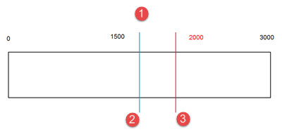
1 - Distance (Sensor Range for a 3mm Sensor)
2 - Offset = 0.000
3 - Offset = 0.500
Graph showing effects of changing the Offset value
Intensity Filter
This value defines the threshold between noise and the measurement signal. Peaks that fall beneath this threshold are recognized as invalid and show on the display as the measurement value "0".
There is no linear relationship between Filter (Sensor Intensity) and "Intensity". For example, if you set Filter (Sensor Intensity) = 50, it doesn't necessarily mean that all values below an intensity of 50 are filtered out.
For a measurement rate under 1kHz, a Filter (Sensor Intensity) minimum of 40 is recommended. This prevents measurement values of too low an intensity, which rise only slightly above the noise, and falsifies the measurement. At a measurement rate of 1kHz and higher, a minimum of 15 is expedient to fully exploit the device’s dynamics.
Focus
The Auto Focus button  reads the current XYZ machine position and the distance value from the
CWS sensor. These values calculate the focus position as well as the Signal
Quality value and displays them in the four Focus
boxes.
reads the current XYZ machine position and the distance value from the
CWS sensor. These values calculate the focus position as well as the Signal
Quality value and displays them in the four Focus
boxes.
Note on Filter Modes
The Speed and Frequency parameters define the point density of the sensor. In the case of scans, PC-DMIS then performs secondary filtering as defined from the Nullfilter and Point Density settings.
Chromatic White Light Sensor Probe Readouts Window
If the Chromatic White Light Sensor (CWS) is the active sensor, the Probe Readouts window displays the X, Y, and Z readouts, plus the following:
Intensity - The value for this readout is a percentage that appears in a circular graphic. An intensity value above 99% indicates a measurement error; for example, the sensor may be out of detection range. If a measurement error occurs, the non-gray part of the graphic turns red.
Distance - The value for this readout is in the current unit of measurement (inches or millimeters). The value appears in a circular graphic. If the distance value is within 10% of the upper or lower limit of the sensor range, the non-gray part of the graphic turns red.
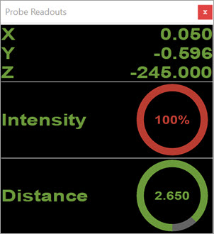
Probe Readouts window showing overmodulation
For these readouts to appear, do not select the CWS Laser tab. Once you select it, the readouts are no longer sent to the Probe Readouts window.
For more details on the CWS Parameters tab on the Probe Toolbox, see "Laser Probe Toolbox: CWS Parameter tab" in the PC-DMIS Laser documentation.
More: