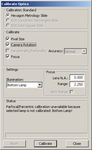
Calibrate Optics dialog box
This option calibrates the optics on the system. PC-DMIS supports four separate calibrations (depending on hardware and the available calibration artifact):
Pixel Size - This calibrates the size of the field of view throughout the zoom cell's magnification (mag) range or with a given optic’s configuration. Follow the manufacturer’s guidelines on optical calibration intervals. You need to recalibrate the optical magnification any time the zoom cell or microscope is altered (such as when it is sent in for repair).
Camera Rotation - This calibrates the rotation of the camera to the stage, and removes any rotation. This is particularly evident on CMM-V systems.
Parcentrality/Parfocality - This calibration ensures that the center of the lens and the center of the field-of-view are aligned. This option is only available if the following are true:
You are using a zoom lens.
The selected lamp was previously calibrated. See "Calibrate Illumination".
You select the Pixel Size calibration.
Focus - Focus Depth and Latency are calibrated through a series of focus adjustments at various magnification levels.
If your zoom cell automatically calibrates, then you won't need to perform a specific magnification calibration. Instead, a message that the calibration is done appears.
To calibrate the optics, do the following:
From the Calibrate Probe dialog box, from the drop-down list, select Calibrate Optics.
Click Calibrate to open the Calibrate Optics dialog box.
Calibrate Optics dialog box
When the calibration procedure starts, DO NOT move the calibration standard.
In the Calibration Standard area, select the calibration standard that corresponds to the type of calibration standard you received with your system. Supported standards include:
HexagonMI Slide
ROI Concentric Rectangle Slide (ROI machine only)
ROI Solid Square Slide (ROI machine only)
From the Calibrate area, select the needed options.
Pixel Size - Calibrates the pixel size at different magnification to determine the size of a measured feature.
Camera Rotation - This option allows PC-DMIS Vision to determine if there is any rotation in the camera relative to the stage and makes the needed adjustments.
Parcentrality/Parfocality - When this option is selected, the parcentrality/parfocality is calibrated using the Pixel Size calibration. This process replaces the need for doing an Optical Center calibration. This option is only available when you use the HexagonMI Slide (Hexagon Manufacturing Intelligence) and when your machine uses a zoom lens. Use the "Calibrate Optical Center" option for machines using a fixed (non-zoom) lens. Also, see the "Parcentricity Calibration Modes" topic.
Accuracy - There are two methods for calibrating parcentrality/parfocality.
Normal does the calibration on the same rectangles that were used for the FOV (pixel size) calibration, and results in a faster calibration process.
High does the calibration on the concentric circles on the calibration standard. This gives better quality results, but takes longer to perform.
Focus - This option performs focus calibration for depth and latency.
From the Settings area, select the calibration settings:
Illumination - Select the Illumination source. Calibration is usually best done using bottom or sub-stage lighting as the edge contrast is sharper. Select <Current> to use the current illumination settings and not change the illumination during calibration. CMM-V can now use its ring light, and defaults to that light source.
Focus - Lens N.A - Specify the numeric aperture (N.A.) of the current lens if known, otherwise leave this box blank. This value allows the calibration program to optimize the focus used during the calibration.
Focus - Range - Specify the focus range if no numeric aperture is given. This provides the range over which the focus is done.
Auto Range - Select this check box to auto calculate best range to use for focus. (This option may not be available on all systems.)
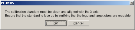
Click the Calibrate button. A message box appears, stating that your calibration standard must be clean and aligned with the X axis. You must also ensure that the standard is face up.
Although the calibration processing employs noise and dirt rejection techniques, a dirty calibration standard may trigger calibration failures or yield less accurate measurement values. Be sure to clean any dust, dirt, fingerprints, or other material from the calibration standard's glass portion. Use a mild non-depositing cleaning solution, such as rubbing alcohol, and a soft, lint-free cloth. Be sure to also clean the stage glass where the calibration standard is positioned. For proper cleaning techniques, refer to your hardware documentation. If the stage carrying the glass standard might move during the calibration sequence, hold the standard to the stage with clay or putty.
Place the calibration artifact on the stage so the length of the standard runs along the X axis of the machine. For the ROI slides, ensure that the larger targets are on the left (-X direction) and the smaller targets on the right (+X direction). Verify the alignment with the X axis by watching the horizontal line on the standard while traversing the stage X axis. The line should remain in the field of view and ideally very near center.
Click the OK button. Additional messages appear, requesting that you center the target.
Place a target so that it completely fits within the camera's view. This target should be roughly centered within the field of view and focused. The focus does not need to be optimal, just a good starting place for the software focus process.
Click the OK button. If you have a DCC machine, it automatically focusses on the target. If you have a manual machine, the software displays a prompt for you to focus on the target.
Use the manual controls to move the optical measuring system and roughly center the rectangle or square calibration standard in the field of view. PC-DMIS determines the target size based on your optics.
Do not change the Z position or the focus during the rest of the calibration procedure.
Click OK after you have centered the target. The calibration routine automatically proceeds based on the calibration options selected:
If the machine supports DCC illumination control, and an illumination lamp has been selected in the Illumination field, PC-DMIS Vision performs a lighting grayscale adjustment where it measures the target (or series of targets) across the range of magnifications.
If the system has Manual Illumination control, you are prompted to increase or decrease the illumination level as required.
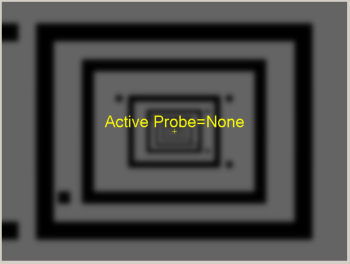
If you select Pixel Size, the system moves to the next target as needed. If you use a manual-only stage, PC-DMIS Vision prompts you to move to the next target. When it prompts you for manual movement of the stage, you should make the X and Y values displayed in the message box as close to zero as possible. This process continues, until sufficient target measurements have been taken.
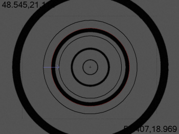
![]()
Pixel Size Calibration
If for parcentrality / parfocality Accuracy, you chose Normal, PC-DMIS Vision performs Parcentrality/Parfocality calibration on the same rectangles used for the Pixel size calibration.
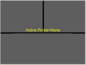
If you chose Focus, the system moves in and out of focus at various levels of magnification. Focus calibrations are done to determine Focus Depth and Focus Latency.
Focus Calibration
If you chose Camera Rotation, PC-DMIS Vision measures the line at the bottom of the slide at different positions a number of times so it can identify the camera to stage rotation. If the rotation angle calculated is greater than 5 degrees, a warning indicates that the hardware should be physically adjusted to make the angle smaller. You can still apply the calibration to compensate, but it is recommend that you get the physical wrist/camera adjusted to the stage. This option is only available when using the HexagonMI Slide.
Camera Rotation Calibration
If for parcentrality / parfocality Accuracy, you chose High, PC-DMIS Vision prompts you to "Align the HexagonMI Standard Concentric Circle in Target". Align the circle as depicted in the image below, and click OK.
Target centered on Concentric Circles of HexagonMI Standard
The Calibration Process continues by focusing and taking a series of measurements at different magnification levels. This establishes that the optical center and focal depth coincide through the focal range. This means if you focus and measure a circle at one magnification, it gives the same XYZ position at another magnification.
Near the end of calibration, PC-DMIS generates and runs a series of dynamic measurement routines in the background. It does this to perform a basic verification that measures a subset of the calibration data. As the software measures each target in these measurement routines, the Status area on the Calibrate Optics dialog box updates its message to show the step number.
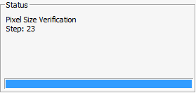
Status Message Showing Pixel Size and Error
When the pixel verification finishes, PC-DMIS may display a Verification Complete dialog box. This dialog box appears only if a verification data point is out of tolerance. The dialog box contains columns showing the different steps that were measured, the pixel size and errors. A <- symbol to the right of the error value indicates that the error is larger than the specified tolerance.
![]()
Verification Complete dialog box
If this dialog box appears, you can click Run Again to rerun the verification. This helps determine if any errors were simply anomalies in the verification. If the verification fails multiple times, try re-running the entire pixel size calibration. If both the calibration and the verification fail repeatedly, contact Hexagon Technical Support.
Click Continue to accept the results of the verification.
The ProbeCal section of the PC-DMIS Settings Editor contains registry entries that affect the pixel size calibration.
Click the Close button to close the Calibrate Optics dialog box. The software also writes the calibration results to the Calibration Results dialog box so that you can view the results of the calibration later. To view the results, click the Results button on the Probe Utilities dialog box:
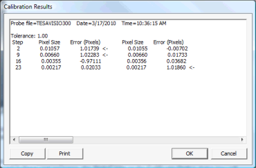
Calibration Results dialog box
You have now calibrated the Field of View. Repeat this process for each lens you wish to use on the machine.
On a CMM-V camera, just the FOV for the A0B0 wrist angle needs to be calibrated. You may wish to place some reflective white paper on the CMM table under the "Calibration Artifact Holder" (Part Num. CALB-0001). The "Calibration Artifact Holder" includes a glass slide (CALB-0002) and a ring gage (CALB-0003) used for calibration of the CMM-V camera.