Once you have created a Vision tip, select Edit from the Probe Utilities dialog box to edit the probe data for the selected tip. Default values are provided according to the defined probe. This opens the Edit Probe Data dialog box.
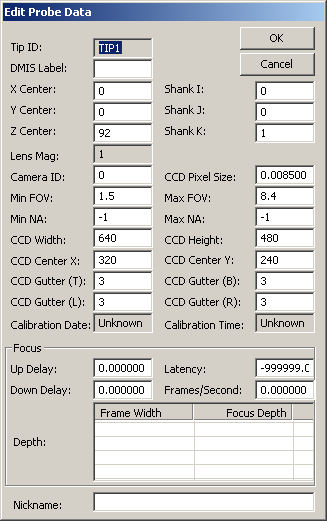
Edit Probe Data dialog box for Vision tips
You can edit or view the following values for your Vision tip as needed according to the defined Vision probe:
Tip ID: Displays the Tip ID for the presented probe data
DMIS Label: This box displays the DMIS label. When importing DMIS files, PC-DMIS uses this value to identify any SNSDEF statement inside the imported DMIS file.
XYZ Center: Center of the focal point of the camera. This is updated by the "Calibrate Probe Offset", so that the camera and touch probe are in the same reference system.
Shank IJK: These three values provide the optical vector for the direction that the optical lens is pointing.
Lens Mag: Displays the magnification of the defined probe lens.
Camera ID: Allows you to provide an ID for the camera that you are using. For dual camera support, an integer indicates whether this tip gets its image from Frame Grabber camera input 0 or 1.
CCD Pixel Size: Pixel size at which image data is evaluated. Smaller values indicate a higher resolution for image capturing.
Min FOV: This value allows you to adjust the minimum allowable field of view size.
Max FOV: This value allows you to adjust the maximum allowable field of view size.
Min NA: This value allows you to provide the minimum allowable numerical aperture.
Max NA: This value allows you to provide the maximum allowable numerical aperture.
The NA is commonly printed on microscope objective lenses and used by the software to estimate appropriate focus ranges. The undefined value is -1.
CCD Width: Provides the width of the video frame of your optical device.
CCD Height: Provides the height of the video frame of your optical device.
CCD Center X: Provides the optical center along X for the video frame.
CCD Center Y: Provides the optical center along Y for the video frame.
CCD Width, Height, and Center XY are used and updated when calibrating the optical center of your Vision probe. See "Calibrate Optical Center".
CCD Gutter (TBLR): These values provide the number of top (T) and bottom (B) rows and left (L) and right (R) columns (in pixels) around the edge of the camera image that should be avoided during calibration and measurement. Some cameras show "dead pixels" in this area.
Calibration Date: Displays the date that your Vision tip was calibrated.
Calibration Time: Displays the time that your Vision tip was calibrated.
Focus Area
Up Delay: Approximate time delay in seconds for focus motion to start and stabilize when focus motion is positive or up.
Latency: Average time in seconds between when the stage position and the video frame data are recorded.
Down Delay: Approximate time delay in seconds for focus motion to start and stabilize when focus motion is negative or down.
Frames/Second: Measured frames per second during focus.
Depth: Table of the field of view X dimension size and the corresponding depth of field factor.
Nickname: User defined name given to the tip.