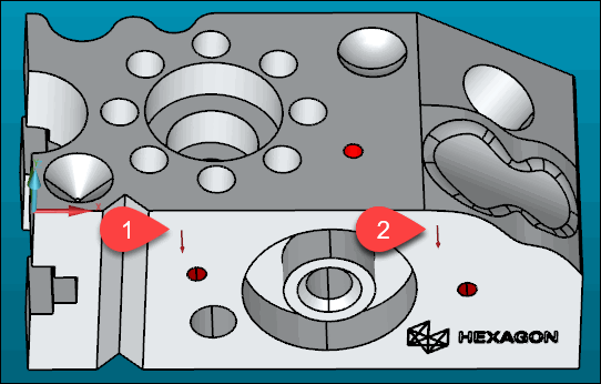
Second, you need to select a line with two or more hits on the front face of the part, just below the edge. This tutorial uses two hits.
The order of the hits for line features is very important. It establishes the direction of the line from the first point to the second. PC-DMIS uses this direction information to create the coordinate axis system.

Red arrow bases show two hit locations
In the Graphic Display window, in the bottom view, move your pointer, below the top edge.
Click the pointer on the front face of the part just below the edge.
Take the first hit on the left side of the front face.
Take the second hit to the right of the first hit on the front face.
Press the End key after two hits to accept the line feature.
PC-DMIS displays a feature ID (LIN1) and draws a line in the Graphic Display window:

A - Line feature in the Z+ view
B - Line feature in Y- view
PC-DMIS also inserts a FEAT/LINE command in the Edit window.