From the main menu, select Edit | Graphic Display Window | CAD Section Cut. The CAD Section Cut dialog box is displayed.

Select the type of section cut you want to define from the Section Type list. For details on these options, see the topic "Cross Section".
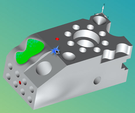
Click the surface where the section cut is to start.
Move your cursor to where the section cut is to end and click.
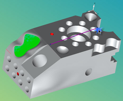
The CAD Section Cut is generated.

From the CAD Section Cut dialog box, edit the properties. Click and drag any of the section cut handles in the Graphic Display window to manipulate the properties.
Click Create to finalize the CAD section cuts.

Once created, the CAD section cuts can be viewed in the CAD Assembly dialog box (Edit | Graphic Display Window | CAD Assembly).
Click Close when done.