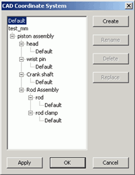

CAD Coordinate System dialog box
The Edit | Graphic Display Window | CAD Coordinate System menu option displays the CAD Coordinate System dialog box. The CAD Coordinate System dialog box lets you create or select new coordinate systems for your CAD model.
The Coordinate System list on the left side of the dialog box shows all the coordinate systems in the CAD model. The coordinate systems listed first are the global coordinate systems. The Default coordinate system is always listed.
If the CAD model is an assembly of component parts then following the global coordinate systems, PC-DMIS lists all the coordinate systems contained in that assembly. These are listed in a tree view structure. To expand the tree view, click on a plus symbol (+). PC-DMIS displays the component parts' assembly coordinate systems. The Default coordinate system is always listed for each part component in the assembly. This coordinate system defines the part's default local coordinate system.
When you first open the CAD Coordinate System dialog box, PC-DMIS checks to see if the current active coordinate system matches a coordinate system in the list:
If it finds a match then PC-DMIS selects it from the list.
If it doesn't match any of the coordinate systems then PC-DMIS uses the Default coordinate system at the top of the list. This can happen if you transformed the CAD without creating a coordinate system (for more information, see the "Transforming a CAD Model" topic).
To Select and Use Coordinate Systems
To use an existing coordinate system:
Select the coordinate system from the Coordinate System list. PC-DMIS shows that coordinate system in the Graphic Display window. If you select an assembly component, PC-DMIS selects the first coordinate system in that component instead.
Click Apply or OK. The selected coordinate system becomes the new active coordinate system, and PC-DMIS redraws the CAD to reflect its new position.
To Create a Coordinate System
To create a coordinate system at the current CAD model's position, click the Create button. You can use the CAD Transform dialog box to change the CAD model's position. For more information on how to transform a CAD model, see the "Transforming a CAD Model" topic.
To Rename a Coordinate System
To rename a coordinate system, select the coordinate system from the list, and click the Rename button. Type the new name.
You cannot rename the Default coordinate system.
To Delete a Coordinate System
To delete a coordinate system, select the coordinate system from the list, and click the Delete button. PC-DMIS deletes the selected coordinate system.
You cannot delete the Default coordinate system or assembly coordinate systems.
To Replace a Coordinate System
To replace or overwrite an existing coordinate system with the current CAD model's position, select a coordinate system from the list, and click the Replace button.
You cannot replace the Default coordinate system or assembly coordinate systems.