Except where specified, the following Rotary Table commands were developed to support the PC-DMIS/NC (Numerical Control) for use on CNC machine tools. However, you can use them in regular CMM measurement routines as well. For more information on how to use CNC machines with PC-DMIS, see the PC-DMIS/NC Help file.
Ignore Rotary Table
When you have a rotary table defined for use, PC-DMIS usually assumes that you place the parts to measure on the rotary table. Essentially, PC-DMIS expects you to use the rotary table.
With the IGNOREROTAB command, you can determine whether the measurement routine uses the rotary table.
The Insert | Parameter Change | Probe | Ignore Rotary Table menu item inserts an IGNOREROTAB command into the measurement routine. The options are as follows:
IGNOREROTAB/OFF
This command means PC-DMIS does not ignore the rotary table. In this state, PC-DMIS adjusts any measured data collected from the machine by using the data from the rotary table's calibration. This is the default state. If you want to measure parts with the use of a rotary table, you do not need to add this command.
IGNOREROTAB/OFF
IGNOREROTAB/ON
This command means PC-DMIS ignores the rotary table. Thus, the measured data that PC-DMIS collects does not have a rotary table adjustment applied to it. This might be used when a part that you want to measure is placed on a CMM table and not on a rotary table. You want to measure the part without using the rotary table even though your table exists.
IGNOREROTAB/ON
IGNOREROTAB/CALIBRATION
This command means PC-DMIS ignores the rotary table. You can use this command when you want to calibrate the rotary table.
How to calibrate the rotary table using measurement routine
To calibrate the rotary table, follow these steps:
Attach a proper calibration artifact (a sphere) to the rotary table.
Add the IGNOREROTAB/CALIBRATION command to your measurement routine.
Measure the sphere at three or more positions of a rotary table.
Construct a plane through the resulting sphere centers.
Create an alignment to level this constructed plane to the axis of rotation of the rotary table.
Construct a circle through the resulting sphere centers.
Once you have constructed the plane and circle, you can use them as inputs to the CALIBRATEROTAB command.
Insert the CALIBRATEROTAB command. To insert the command, select the Insert | Calibrate | Rotary Table from Features menu item.
CALIBRATEROTAB/PLANE=TABLE_PLN, CIRCLE=TABLE_CIR,
MEAS/XYZ=0,0,0, MEAS/IJK=0,0,0
This command tells a suitable measurement routine to calibrate the rotary table during measurement routine execution.
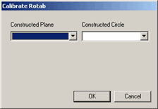
Press F9 on the command to display the Calibrate Rotab dialog box.

Calibrate Rotab dialog box
From the Constructed Plane list, select the constructed plane in step 4. From the Constructed Circle list, select the constructed circle in step 6.
Click OK. PC-DMIS updates the command to use the constructed features.
When you execute the measurement routine, PC-DMIS uses the constructed features to update the rotary table calibration data. The MEAS/XYZ and MEAS/IJK portions in the command block show the result for the center point and plane of rotation for the table.
For information on how to set up your rotary table, see the "Defining the Rotary Table" topic in the "Setting Your Preferences" chapter.
Rotate the Table to the Active Angle (Not Supported in PC-DMIS NC)
The actual rotary table angle on the machine and the active angle specified in your measurement routine don't always match. The Operation | Rotate Table to Active menu item automatically causes the actual table to rotate until its angle matches the active angle in the measurement routine at your cursor's location.
More: