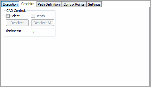

Graphics tab from a scan dialog box
The Graphics tab in the scan dialog box (Insert | Scan) lets you use the on-screen CAD model to aid in creating a scan. This tab contains the CAD Controls area. This area lets you specify the CAD surface/wireframe elements that will be used to find nominals as well as the part's thickness.
In some cases, a scan might start over a certain surface and travel over many other surfaces before completion. In such cases, PC-DMIS does not know which CAD elements are to be used to find nominals. It must therefore search through every surface in the CAD model. If the CAD model has many surfaces it might take a long time before the FINDNOMS operation is successful.
The Graphics tab has these options:
Select check box

Selecting this check box and clicking on surfaces lets you define the exact surfaces to scan. Manually determining the surfaces to scan helps speed up the FINDNOMS process. Once a CAD surface is selected, it is highlighted in the Graphic Display window. The Status bar displays the number of surfaces that have been selected. If the Select check box isn't selected, PC-DMIS assumes any clicks on the surface to be Boundary Points.
Two edges that are normal to each other must be selected for every surface the scan is going to travel over. If the scan is going over three surfaces, six edges (representing the three surfaces) must be selected in the proper order. The first two edges indicate surface one. The third and fourth edges indicates surface two. Edges' five and six make up the third surface, and so on.
Deselect button

If you select an incorrect surface, click on that surface a second time. This will deselect the surface. Clicking the Deselect button will deselect one surface at a time with each click of the button from a group of highlighted surfaces until all are deselected. Clicking the Deselect All button will deselect all highlighted surfaces at once.
The Deselect button removes one highlighted CAD element at a time from a group of CAD elements that are created using the Select check box.
Deselect All button

The Deselect All button removes all the selected CAD elements that are created using the Select check box.
Depth
check box
This check box is used only when selecting Curve elements. You can indicate
a particular CAD curve element as a Depth element.
To use the Depth check box:
Select all other CAD elements first.
Select the Depth check box.
Select a CAD element.
The Depth curve is used during FINDNOMS operations. Whenever PC-DMIS has to find nominals from curve elements, it will take the vector of the Depth CAD element, cross it with the vector from the other selected CAD elements to get a plane. It will then pierce the plane to get the proper nominal. If many CAD elements are selected, the closest pierce point is used as the nominal point. When CAD wireframe data is being used, PC-DMIS will look for the wireframe data in pairs.
vector1 check box

The vector1 check box only appears if you select Angle from the Hit Type list and you are using surface data. It allows you to select CAD surfaces that PC-DMIS will use to find the nominal. You can indicate the group of surfaces that PC-DMIS uses to find the angle hit Surf 1 Vec by selecting this check box and then selecting CAD surfaces from the Graphic Display window.
vector2 check box

The vector2 check box only appears if you select Angle from the Hit Type list and you are using surface data. It allows you to select CAD surfaces that PC-DMIS will use to find the nominal. You can indicate the group of surfaces that PC-DMIS uses to find the angle hit Surf 2 Vec by selecting this check box and then selecting CAD surfaces from the Graphic Display window.
Thickness box

The Thickness box allows you to input the part thickness. Positive or negative values can be used. This amount is primarily used for thin parts (plastic or sheet metal) where the CAD data only describes one side. Often with thin parts, the CAD engineer will only draw one side of the part, and then specify the material thickness. PC-DMIS will apply this material thickness automatically when using the CAD surface data.
This thickness is applied along the surface normal vector when FINDNOMS mode is selected and PC-DMIS pierces the CAD surfaces to get the nominals, even when using Edge hits.