You can use the Insert | Report Command | Snapshot menu item to display screen captures of the part in your report.
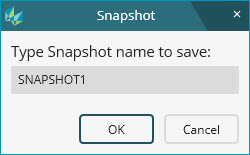
When you select the menu item, a Snapshot dialog box opens so you can type the snapshot name:

Snapshot dialog box
The Insert Snapshot button ( ) on the Graphic Modes toolbar
also opens this dialog box.
Once you define a name, PC-DMIS then inserts a SNAPSHOT command with that name in the Edit window. When this command is marked and executed, PC-DMIS automatically refreshes the screen capture and displays it in the report.
In the Edit window in Command mode, you can also manually type SNAPSHOT and press Tab. When you press Tab, PC-DMIS stores the properties for the state of the Graphic Display window in the command. During execution, PC-DMIS inserts the capture into the report the moment the software executes the command.
Command line in the Edit window:
TOG1 =SNAPSHOT/
TOG1 = This field holds the name of the snapshot.
Differences from the DISPLAY/METAFILE Command
The SNAPSHOT command provides better screen captures than the DISPLAY/METAFILE command. While the snapshot functionality is similar to DISPLAY/METAFILE, it has these differences:
A SNAPSHOT command updates the various analysis-related items you see on the Graphic Display window in the screen capture. These analysis items include graphical analysis, pointcloud color maps, dimension info labels, scan arrows with deviation colors, and so on. DISPLAY/METAFILE results in a much more static image.
A SNAPSHOT command saves your screen orientation and zoom level.
A SNAPSHOT command works with multiple views.
Default Snapshot Names
If you don't type a snapshot name, the default names follow this pattern SNAPSHOT1, SNAPSHOT2, SNAPSHOT3... and so on.
If you first select a CAD model view from the list on the CAD Setup toolbar and then access the Snapshot dialog box, the default pattern follows the name of the current model view.
Suppose you have a CAD model view with the name of Right to show the right side of your part. If you select Right from the list and then access the Snapshot dialog box, the snapshot name shows to "Right1". If you do it again, the next snapshot name shows "Right2", and so on.
Inserting a Snapshot Command
In the Graphic Display window, pan, zoom, and rotate your part to the way you want it.
From the Graphic Modes
toolbar, click Insert Snapshot ( ) to show
a Snapshot dialog box.
In the Snapshot dialog box, type a name for the screen capture.
Click OK to insert the SNAPSHOT command at the selected spot in the Edit window.
If PC-DMIS cannot insert at the current position, it shows a message box that asks how you want to handle the insertion. You can choose one of these three items on the message box:
Next Position - This inserts the command at the next valid position.
End of Program - This inserts the command at the end of the measurement routine.
Don't Insert - This does not insert the command.
Viewing the Snapshot in the Graphic Display Window
Select the SNAPSHOT command in the Edit window.
Press Ctrl + E to execute only that command. This shows the snapshot in the Graphic Display widow.
Updating a Snapshot Command from the Graphic Display Window
From the Edit window, select the SNAPSHOT command you want to update.
Press F9 to open its Snapshot dialog box. The Graphic Display window loads the view stored in the snapshot.
In the Graphic Display window, pan, zoom, and rotate your part to the way you want it for the updated snapshot.
If you like, modify the name.
Click OK to update that snapshot with the new Graphic Display window properties.
Updating a Snapshot Command from Your Report
Execute the routine and then select View | Report Window to access the report in the Report window.
From the Report window, double-click on the snapshot image to convert it into a CADReportObject (CRO).
Pan, zoom, and rotate on the part model in the CRO to modify it. For information on working with the CRO, see "CadReportObject" in the "Reporting Measurement Results" chapter.
Double-click outside of the CRO to accept your CRO changes to the report. PC-DMIS applies these same CRO changes to your SNAPSHOT command in the Edit window. Subsequent executions of that command use the updated SNAPSHOT command.
Adding Snapshots into Custom Reports
In the Report window, edit a custom report, or create a new custom Report. (For information on custom reports, see "Creating Custom Reports" in the "Reporting Measurement Results" chapter.)
From the Edit window in Summary mode, select the snapshot command you want in your report.
Drag and drop it into the custom report to see the screen capture.
Deleting Referenced Commands
Any command in the Edit window that creates a visible element in the Graphic Display window (such as a Dimension Info box) is considered a referenced command by the snapshot command. This means that the snapshot command needs that referenced command to create its screen capture. Snapshot commands cannot reference commands that don't exist. Therefore, if you delete any of these referenced commands, PC-DMIS asks if you want to also delete the associated snapshot commands.