
The SectionCutObject lets you define a section cut (cutaway view) of the CAD model. You can insert a SectionCutObject into the Report Template Editor as with other objects, or you can insert it into a final report page on the Report window directly. To insert this object, position the mouse pointer, and click and drag a box. When you release the button, the object appears, and—at least in the Report Template Editor—it displays "No Image!" until you move the clipping plane so that it intersects with the CAD model. You can move the clipping plane through the object's properties.
Changing the Object's Properties
If you insert the SectionCutObject into the Report Template Editor, right-click on it to access the object's Properties dialog box. You can modify the properties directly in the Properties dialog box or select the (Settings Dialog) property, and click the ... button to use the Section Cut Settings dialog box to more easily modify its properties.
If you insert this object on-the-fly into a report page of the Report window, the same Section Cut Settings dialog box appears.

Section Cut Settings dialog box
You can use this dialog box to define a cutaway image of your part model that you want to show in your report.
Defining a Cutaway Image Using the Section Cut Settings Dialog Box
Fill out the X, Y, and Z boxes to define a point on the CAD model where the clipping plane intersects with the model.
Fill out the I, J, and K boxes to define the direction the plane faces.
Modify the Tolerance value as needed.
Click the Load button to see a live preview of the cutaway image in the Section Cut Settings dialog box.
Use the large left and right
arrow icons ![]()
![]() to fine-tune the placement of the plane and get the exact cutaway
view that you need. The preview in the dialog box updates to match
the placement of the plane.
to fine-tune the placement of the plane and get the exact cutaway
view that you need. The preview in the dialog box updates to match
the placement of the plane.
Reposition the image as desired. Pan the image by right-click dragging. Zoom in or out on the cutaway image by right-clicking above or below the imaginary horizontal line that splits the image view. 2D rotate the part image by holding the Ctrl key and right-click dragging.
Finally, place callouts onto the dialog box image by using the Add Tag button.
Click OK to accept your changes.
You must have an active Internet connection to see this video.

Section Cut Settings Dialog Box Items
X Y Z boxes
These boxes define a point on the CAD model where the clipping plane cuts
the model.
I J K boxes
These boxes define the IJK direction vector of the clipping plane.
Tolerance box
The tolerance parameter is used to:
Check if the polyline is closed. The start and end point distance is less than the tolerance value.
Reduce the polyline.
Merge polylines.
Load button
This button previews the section cut line on the CAD image as well as the
section cut profile.
Hide Image check box
This check box hides the section cut profile image in the Preview window.
If you click the OK button, PC-DMIS also hides
the section cut profile image in the Report Template Editor or on the
Report window's page.
Move clipping plane along above
IJK area
This area contains an edit box and arrow buttons.
The edit box defines the distance that the clipping plane moves when you click the left arrow or right arrow button.
The arrow buttons move the clipping plane along the IJK vector by the specified distance with each click.
If you have 1,0,0 then the plane moves along the X axis.
If you have 0,1,0 then the plane moves along the Y axis.
If you have 0,0,1 then the plane moves along the Z axis.
Add Tag button
This button allows you to place callouts on the cutaway image of the part
model.
Clicking this button changes your cursor to a cross-hair icon. You can click and drag a leader line on the cutaway image in the dialog box. When you release the mouse button, a small text box appears, which allows you to type the callout text. The number of characters this text box can display is only limited by the size of the text box. Increasing the size of the box allows it to hold and display more characters.
You should place tags on the image only when the cutaway image has been completely finalized. If not, the tag is deleted with future modifications to the image.
OK and Cancel
buttons
Clicking OK applies your changes to the section
cut profile image and displays the image in the Report Template Editor
or Report window. If your report contains a CadReportObject, the section
cut line appears on the CAD image.
Clicking Cancel closes the dialog box without applying your changes. However, if you've added the object on-the-fly into your Report window, the SectionCutObject still exists. If desired, you can remove it by right-clicking on the object and selecting Remove Object.
Object Properties
Bottom
Common Properties
Enable
Common Properties
EventReportData
About Events and Visual Basic Code
Font
Common Properties
Hide Image
See description in table describing dialog box items above.
Left
Common Properties
Plane Anchor X
See description in table describing dialog box items above.
Plane Anchor Y
See description in table describing dialog box items above.
Plane Anchor Z
See description in table describing dialog box items above.
Plane Vector I
See description in table describing dialog box items above.
Plane Vector J
See description in table describing dialog box items above.
Plane Vector K
See description in table describing dialog box items above.
Right
Common Properties
(Settings
Dialog)
This property displays the Section Cut Settings
dialog box.
Tolerance
See description in table describing dialog box items above.
Visible
Common Properties
Defining On-The-Fly Section Cut Profiles
Perhaps the easiest way to use section cut profiles is to define them using an on-the-fly creation method within the final report in the Report window itself. To do this:
Right-click on the Report window. A shortcut menu appears.
Select the Add Object on Page | Section Cut Profile menu item.
Click and drag a box directly on the Report window with the size of the cutaway image you want. When you release the mouse button, the Section Cut Settings dialog box appears.
Use the dialog box to define the cut profile as described above. PC-DMIS inserts the section cut profile into the Report window.
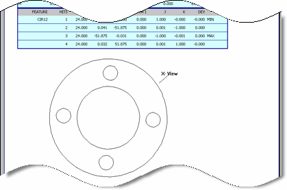
Sample Section Cut Profile
Modifying Section Cut Profiles in the Report Window
Right-click on the object and select Edit Object from the resulting shortcut menu.
