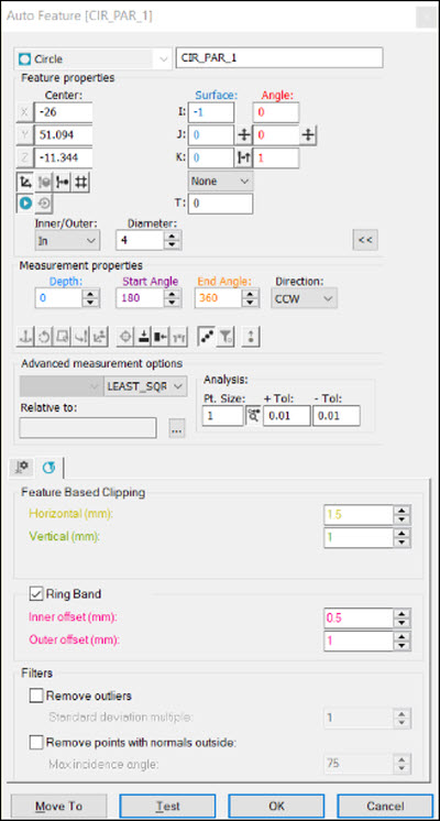
You can measure a fraction of a laser auto circle. You may need to measure a fraction of a circle in these cases:
The start and end angles are already defined on the CAD model.
A complete circle is defined on the CAD model, but the actual pointcloud data is inconsistent.
The start and end angles may be defined the wrong way on the CAD model.
These are the features and parameters that you can use to measure a fraction:
Single-click on the CAD model to enable PC-DMIS to learn the start and end angles.
Define the start and end angles. You can type the angles in the Start Angle and End Angle boxes in the Measurement Properties area in the Auto Feature dialog box. For more information about these boxes, see "Circle-Specific Parameters".
Edit all of the laser auto circle's features, including the direction (clockwise or counterclockwise). For more information, see "Circle-Specific Parameters".
A pointcloud that represents an entire part might contain millions of points. PC-DMIS passes all the parameters to the segregation routine. A segregation routine is a piece of code that creates a subset of the given pointcloud. The horizontal and vertical clipping parameters limit the subset. PC-DMIS then extracts the geometric element from this subset. This is easier and faster than from an entire pointcloud.
Command Mode Example
Here is an example of the Edit window in Command mode:
CIR_PARA_1 =FEAT/LASER/CIRCLE/DEFAULT,CARTESIAN,IN,LEAST_SQR
THEO/<-26,51.094,-11.344>,<-1,0,0>,4
ACTL/<-26.013,50.113,-11.55>,<-0.9578033,0.0757769,-0.2772556>,2.177
TARG/<-26,51.094,-11.344>,<-1,0,0>
DEPTH=0,START ANG=200,END ANG=340
ANGLE VEC=<0,0,1>
DIRECTION=CCW
SHOW FEATURE PARAMETERS=YES
SURFACE=THICKNESS_NONE,0
RMEAS=NONE,NONE,NONE
GRAPHICAL ANALYSIS=YES,0.5,0.01,0.01
SHOW_LASER_PARAMETERS=YES
REFERENCE ID=COP1
HORIZONTAL CLIPPING=2,VERTICAL CLIPPING=1
RINGBAND=ON,INNER OFFSET=0.5,OUTER OFFSET=1.5
OUTLIER REMOVAL=OFF
REMOVE POINTS WITH NORMALS OUTSIDE=OFF
Summary Mode Example
Here is an example of the Edit window in Summary mode:
FEAT/LASER/CIRCLE/DEFAULT,CARTESIAN,IN,LEAST_SQR
THEO/<-26,51.094,-11.344>,<-1,0,0>,4
ACTL/<-26.013,50.113,-11.55>,<-0.9578033,0.0757769,-0.2772556>,2.177
TARG/<-26,51.094,-11.344>,<-1,0,0>
DEPTH=0,START ANG=200,END ANG=340
ANGLE VEC=<0,0,1>
DIRECTION=CCW
CAD Selection Example
Here is an example of the Auto Feature dialog box, CAD model, and Edit window:

Auto Feature dialog box
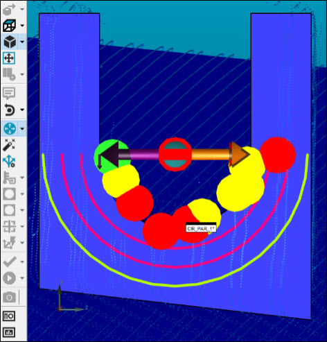
CAD model
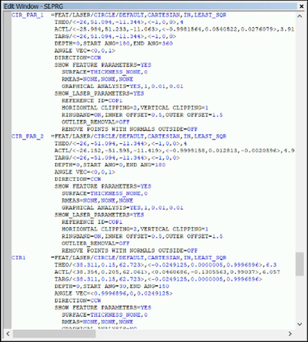
Edit window
Part Variance Example
Here is an example of the Auto Feature dialog box, CAD model, and Edit window for removing the part variance:
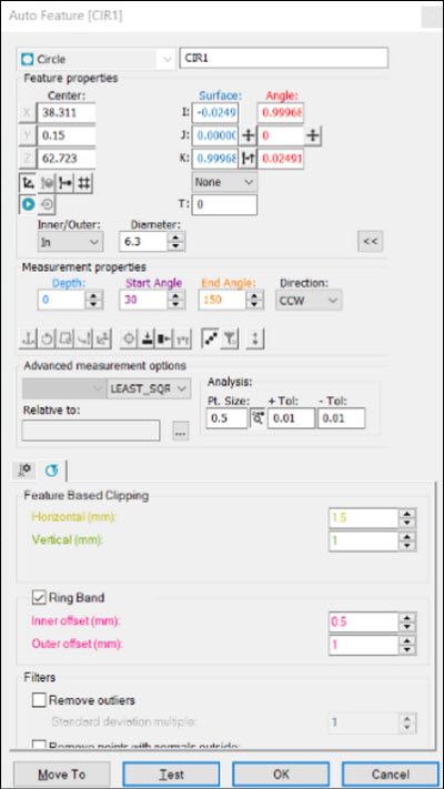
Auto Feature dialog box
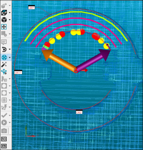
CAD model
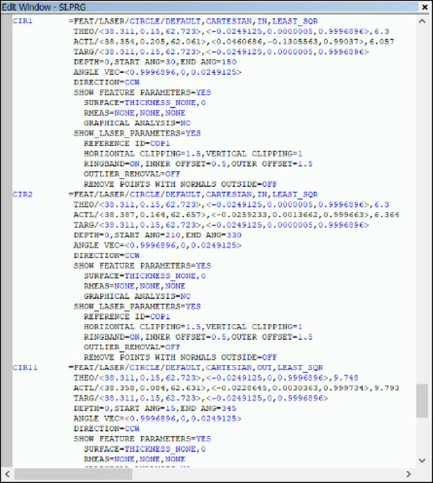
Edit window