The software extracts the nominal and measured start and end points of the Caliper gage when:
You create the Caliper
You execute the Caliper in the measurement routine
The software uses the start and end points to calculate the mid point. The mid point is then projected to the selected axis.
These points are not individual features in the Edit window. They are internal components of the Caliper gage.
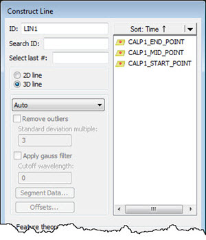
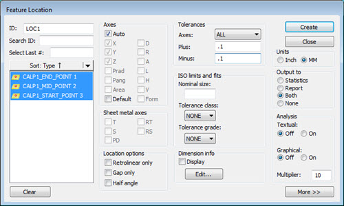
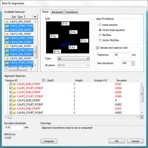
The start point, mid point, and end point automatically appear as constructed offset points in the Dimension, Construction, and Alignment dialog boxes. You can dimension the points and use them in a best fit alignment, such as when you align a cast part that has excess material.
The following examples show various uses of the Caliper start, mid, and end points when you create features and alignments:

Example of start, mid, and end point options when creating a constructed feature

Example of start, mid, and end point options when creating a Feature Location Dimension

Example of start, mid, and end point options when creating an alignment
This example shows the use of the Constrain and Offset methods when you define a Caliper feature:

Examples of the Caliper points using the Constrained (left) and Offset methods (right)
(A) - Caliper1 end points constrained to Y axis
(B) - Caliper2 end points offset to Y axis