The Pointcloud to Pointcloud alignment functionality allows you to best fit align two pointclouds which have been collected in two different reference frames that have some overlap. A typical example is two scans in two pointcloud commands, representing areas of a part that cannot be scanned in the same part orientation.
The alignment is done in two steps:
A rough alignment, where pairs of points in the overlapping area of the two pointclouds are selected.
A refined bestfit, which tries to bring the second pointcloud as close as possible to the reference pointcloud.
To create a Pointcloud to Pointcloud alignment, do the following:
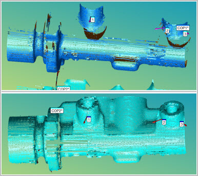
Ensure that you have two or more COP commands in the measurement routine that you are using to align. These elements are required to align two pointclouds.
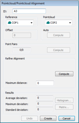
Select the Insert | Pointcloud | Alignment menu option. You can also access this dialog box by typing the COPCOPBF command in the Edit window’s Command mode between the ALIGNMENT/START and the ALIGNMENT/END commands. The dialog box appears:
Pointcloud/Pointcloud Alignment dialog box
For a complete description of the dialog box, see the topic "Pointcloud/CAD Alignment Dialog Box Description".
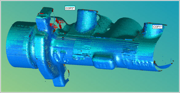
A temporary split-screen view of the two pointclouds appears in the Graphic Display window. You can use this view to visually see the alignment taking place. Select the first COP to be used as a point of reference from the Reference drop down list.
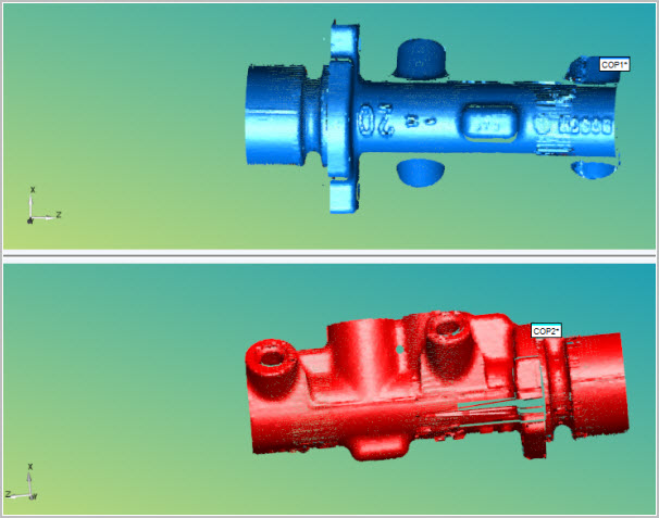
Split-screen view showing a pointcloud to pointcloud alignment
Use your mouse to manipulate and orient each view as needed to create the Point Pairs.
Perform the alignment:
First, use the Point Pairs area to perform a rough alignment that brings the pointclouds close enough to each other. This is a mandatory step.
Click a desired number of points (at least
three pairs) on each of the pointclouds within the overlap area. ONLY
click points on the overlap area of the two pointclouds. 

The more points you take around the overlap area of the pointclouds results in an improved alignment. Click Compute to create the rough alignment.
Next, use the Refine Alignment
area whenever you want to refine your alignment, thereby bringing
the two pointclouds closer to each other. In order to get a good refined
alignment, the two pointcloud points should be close enough to each
other through the initial rough alignment.
Define the maximum distance between the points in the two pointclouds using the Maximum Distance box. The default value is 0 (zero). If the default value is used, PC-DMIS uses an internal default value related to the dimensions of the pointclouds.
Click Compute to refine the alignment.
If a portion of one pointcloud doesn't align nicely with the other, you can click the Undo button and recompute the alignment using the same type of alignment with additional parameters, or you can try a different alignment.
Once you're satisfied with the alignment, click Create. PC-DMIS closes the temporary split-screen view and places the COPCOPBF command in the Edit window. For details on the COPCOPBF command, see the "COPCOPBF Command Mode Text" topic in the PC-DMIS Laser documentation.