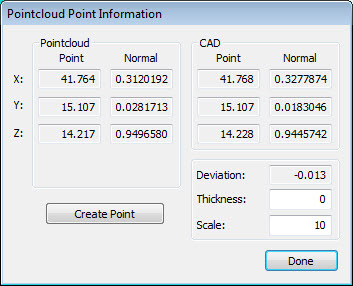
With the Pointcloud Point Information dialog box, you can view point-specific information.
To access this dialog box:
Click the COP command in the Edit window to select it and then press the F9 key. The Pointcloud dialog box for the COP command appears.
Click a point on the cloud of points (COP) in the Graphic Display window. The Pointcloud Point Information dialog box appears.

Pointcloud Point Information dialog box
From this dialog box, you can view the XYZ and the Normal point vector values for the Pointcloud point, as well as the ID for the selected point. It also shows the corresponding CAD's XYZ and Normal vector values.
Deviation - Displays the distance from the Pointcloud point to the corresponding CAD point.
Thickness - The software adds this value to the deviation from the CAD value that it computes when you click on a Pointcloud point. This value is useful, for example, if you have a CAD surface model and you want to add a material thickness.
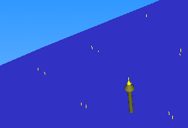
Scale - This value determines the scale that the deviation arrow uses in the Graphic Display window. For example, A scale of 10 displays an arrow with a length that is ten times the length of the deviation.
The deviation arrow appears when you select a point from the Graphic Display window. The arrow indicates the direction of the point deviation from the CAD.

Point Deviation Arrow
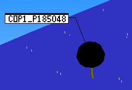
Create Point button - This creates a constructed offset point for the selected point. The software names the constructed offset point with the following convention and then adds the point to the measurement routine: <pointcloud name>_P<point ID> (for example, COP1_P185048).
If you use a laser sensor when you click Create Point, the software creates a laser surface point instead of a constructed offset point.

Constructed Point from Pointcloud
Using Point Data for Auto Features
With the Auto Feature dialog box open, you can click on desired points from the pointcloud to provide input data for a given auto feature. For more information, see "Auto Feature Extraction".