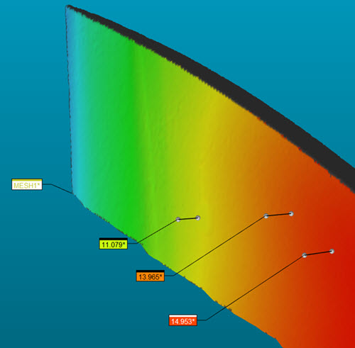
To understand how PC-DMIS measures the annotation point, you can display the initial clicked point, the point on the opposite side of the part thickness and the connecting line. Click the Show annotation opposing points check box to enable this function.
You can change the size of the annotation points and the thickness of the connecting line from the Pointcloud area of the OpenGL tab on the CAD and Graphic Setup dialog box (Edit | Graphic Display Window | OpenGL). For details, see "Changing OpenGL Options" in the "Setting Your Preferences" chapter of the PC-DMIS Core documentation.

Thickness Colormap example with the "Show annotation opposing points" check box selected
More:
Compare to CAD Thickness Colormap
Show the Thickness Colormap in the Report
Thickness Colormap Annotations