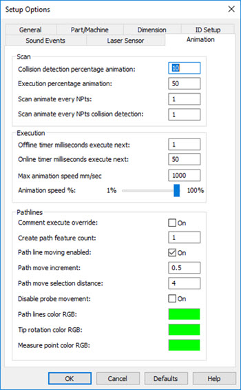
You can control the speed of the simulated laser scan in the Scan and Execution areas on the Animation tab of the Setup Options dialog box (Edit | Preferences | Setup, or press the F5 key). For details, see "Setup Options: Animation Tab" in the PC-DMIS Core documentation.

Setup Options - Animation tab
Scan Area
Scan animate every NPts - This value determines the number of scan path points that PC-DMIS uses for the animation.
For pointcloud simulation, if you enter a value of "1", the software uses every scan point, which results in a smoother animation.
If you use a larger value (for example "10") for pointcloud simulation, the laser scanner probe moves from point 1 to point 10 and immediately shows all the purple pointcloud stripes between those scan path points. The result is a faster but less-smooth animation. The default value is 50.
You can also set this value in the PC-DMIS Settings Editor. For details, see "ScanAnimateEveryNPts" in the PC-DMIS Settings Editor documentation.
Execution Area
For Pointcloud simulation, the values in this area are typically set to the maximum values.
Max animation speed mm/sec - This lets you define the maximum animation speed that the animated probe will use in the Graphic Display window during measurement routine execution. The speed is in mm per second. You may find it useful to alter this value for complex measurement routines where the animation renders too slowly. To increase the duration between redrawn views of the animation, increase this value. This causes the software to draw fewer animation steps.
You can also set this value in the PC-DMIS Settings Editor. For details, see "MaxAnimationSpeed" in the PC-DMIS Settings Editor documentation.
Animation speed % - The slider allows you to adjust the actual percentage of the Max animation speed mm/sec value PC-DMIS uses.
You can also set this value in the PC-DMIS Settings Editor. For details, see "AnimateSpeed" in the PC-DMIS Settings Editor documentation.