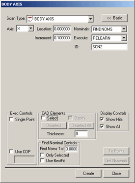
The Body Axis method of scanning allows you to scan a part by specifying a cut plane on a certain part axis and dragging the probe across the Cut Plane. As you scan the part, you should scan so that the probe crisscrosses the defined Cut Plane as many times as desired. PC-DMIS then follows this procedure:
PC-DMIS gets data from the controller and finds the two data hits that are closest to the Cut Plane on either side as you crisscross.
PC-DMIS then forms a line between the two hits which will pierce the Cut Plane.
The pierced point then becomes a hit on the Cut Plane.
This operation happens every time you cross the Cut Plane, and you will finally have many hits that are on the Cut Plane.
You can use this method to inspect multiple rows (PATCH) of scans by specifying an increment for the cut plane location. After scanning the first row, PC-DMIS will move the cut plane to the next location by adding the current location to the increment. You can then continue scanning the next row at the new Cut Plane location.
For information on this tab's other controls, see the "Common Functions of the Scan Dialog Box" topic in the "Scanning Your Part" chapter in the PC-DMIS Core documentation.
To create a Body Axis scan:
Select the Insert | Scan | Body Axis menu option to open the BODY AXIS dialog box.

BODY AXIS dialog box
Specify a custom name for the scan in the ID box if you don't want to use the default name.
From the Axis list, select an axis. The available axes are X, Y, and Z. The cut plane that your probe will crisscross will be parallel to this axis.
In the Location box, specify a distance from the defined axis where your cut plane will be located.
 In
the Increment box, specify the distance
between planes if you will be scanning across multiple planes.
If you're using a CAD model, type a Find Nominals tolerance in the Find Nominals Control area. This defines how far away the actual ball center point can be from the nominal CAD location.
Set any other dialog box options as needed.
Click Create. PC-DMIS inserts the basic scan.
Execute your measurement routine. When PC-DMIS executes the scan, the Execution Options dialog box appears, and PC-DMIS waits for data to come from the controller.
Manually drag the probe back and forth over the surface you want to scan. As the probe approaches a defined cut plane, you will hear a continual audible tone that gradually increases in pitch until the probe crosses the plane. This audible cue helps you determine how close the probe is to any cut planes. PC-DMIS will accept hits from the controller each time the probe crosses the defined plane.