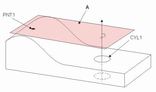
A - Plane constructed perpendicular to a cylinder feature (CYL1) and through a High Point feature (PNT1). Note that CYL1 contains an axis element.
A plane can be constructed between supported features. PC-DMIS creates a plane perpendicular to the first input feature and passing through the centroid of the second input feature.
To construct a perpendicular plane:
Access the Construct Plane dialog box (Insert | Feature | Constructed | Plane).
Select the Perpendicular option.
Select the first feature type. This must be a plane, line, or axis element.
Select a second feature of any type.
Click the Create button.
The Edit window command
line for this option reads:
CONSTR/PLANE,PRTO,feat_1,feat_2
A - Plane constructed perpendicular to a cylinder
feature (CYL1) and through a High Point feature (PNT1). Note that CYL1
contains an axis element.
Constructing a Perpendicular Plane
By default, the vector of the constructed plane is calculated based on the vector from the first feature to the second feature. You may not always want this. The Coplaner with line check box lets you specify how PC-DMIS calculates the vector of the resulting plane. This check box becomes enabled for selection only when the following conditions are met:
The first feature must be a plane type feature (plane, circle, or slot).
The second feature must be a line type feature (line, cylinder, or cone).
The vectors of the two features must not be parallel.
If you mark this check box, PC-DMIS constructs the resulting plane to be coplaner with the second feature.