This probe changer is used with the DSE rotating head. It is defined as ZEISSTC_DSE. To perform the calibration for this probe changer, place the special probe changer calibration tool inside the slot.
For this probe changer to function properly, each slot must be assigned the same number as in the Zeiss software. For example, if there are four slots (typically back to back), the proper setup is as follows:
Define ToolChanger1 with two slots.
Assign to Slot #1 the slot that Zeiss software calls Slot #1 (or A).
Assign to Slot #2 the slot that Zeiss software calls Slot #2 (or B).
Define ToolChanger2 with four slots (slots #1 and #2 will not be used).
Assign to Slot #3 the slot that Zeiss software calls Slot #3 (or C).
Assign to Slot #4 the slot that Zeiss software calls Slot #4 (or D).
The proper INI settings for the DSE tool changer are as follows:
[ZEISS]
TCDepthClearance = -47.360000
TCLengthClearance = 31.800000
TCVerticalClearance = 153.750000
TCVerticalStroke = 10.000000
TCLengthInFrontOfSlot = 120.000000
TCVerticalDropToRealDropoff = 112.000000
TCLengthBackOutOfSlot= 15.000000
TCUsingCalibrationTool = TRUE
Note that these values were used with older versions of PC-DMIS (for example, version 2.X).
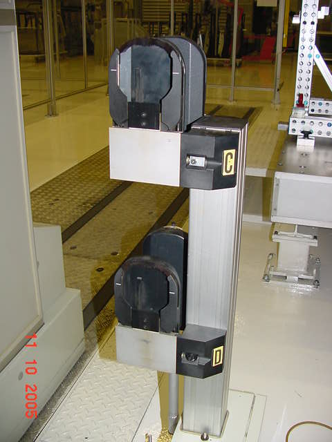
An example of these systems is shown below. This is the left-hand side of a GPIB-based, dual-arm system, which has a 4-slot tool changer. The front two slots (shown here as C and D) must be defined within PC-DMIS as one tool changer, and the rear two slots (A and B) must be another.
Single-Arm Calibration
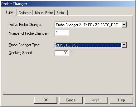
To do a single-arm calibration, consider slot 3 of the right-hand arm on a UDP-based, dual-arm system. Complete the Type tab in the Probe Changer dialog box as follows:
Complete the Calibrate tab as follows:
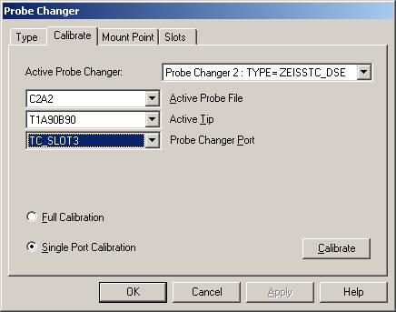
Ensure that the correct probe changer, slot, and tip angle are selected, and select the Calibrate button. The following message appears:
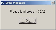
Select OK. The following message appears:
Assuming that it is safe, select OK. The following message appears:
Use the jog box to disable the current tool.
Manually remove the tool.
Manually insert the calibration tool.
Use the jog box to enable the calibration tool.
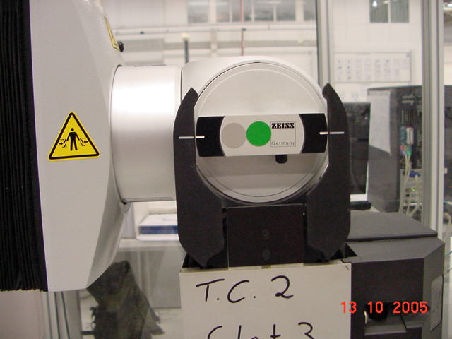
Use the jog box joystick controls to move the calibration tool into position at slot 3 as shown below:
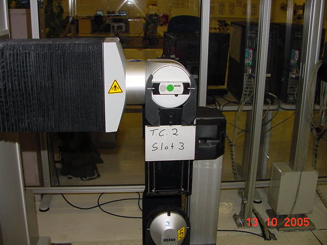
For details on jog box manual tool changing controls, see the "Jog Box Manual Tool Changing Controls" section in this topic.
In this case, Slot 3 is clearly marked. Below it, slot 4 can be seen with a tool present. The side view is shown below:
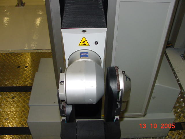
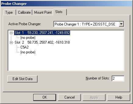
On the right-hand side of the picture, slot 1 can be seen with a tool present. It is possible to manually drop tools into and lift them out of the tool changers if necessary. Slot 2 is below slot 1, and this pair is defined in PC-DMIS as tool changer 1 with head angles A=-90, B=-90.
When calibrating the calibration, the tool should be flush with the front of the toolchanger. The marks should line up accurately as shown below:
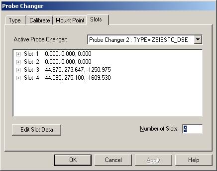
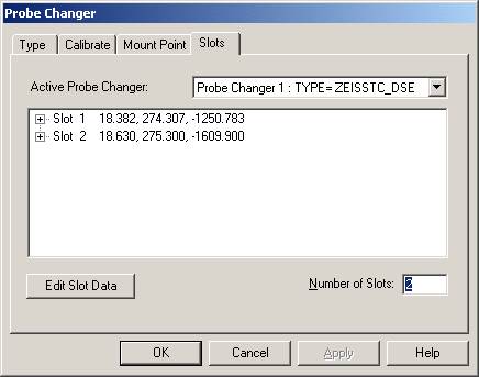
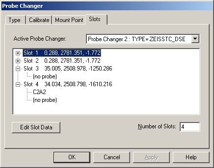
Select the OK button when in position, and inspect the new coordinates on the Slots tab. Note that slots 1 and 2 are redundant for probe changer 2:
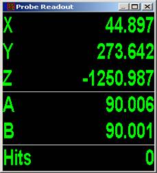
If you position the cursor in the PC-DMIS Edit window before you define any probe, then the coordinates in the dialog box should agree with the current coordinates that PC-DMIS displays in the Probe Readouts window. In this case, our slot 3 calibration verifies nicely:
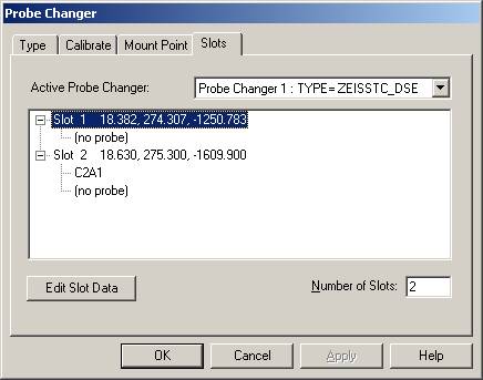
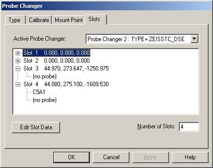
Finally, update the Slots tab in the dialog box to define the required tool for each slot. In this case, C5A1 will be stored in slot 4, and slot 3 remains unused:
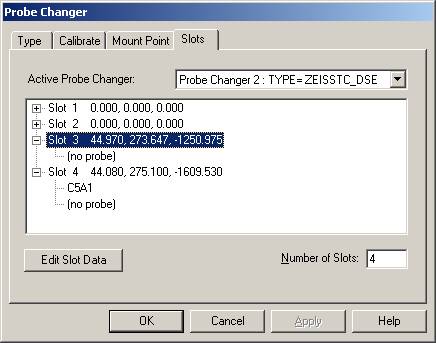
Note that slots 3 and 4 do not need to be included for tool changer 1:
Multiple-Arm Calibration
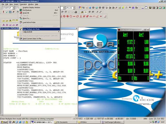
In a dual-arm system (such as the one above), it is preferable to calibrate tool changers for both arms from the Master (Arm1) PC. For this, select Multiple Arm mode as shown below:
Use the red and green buttons to select the arm on which calibration is required:
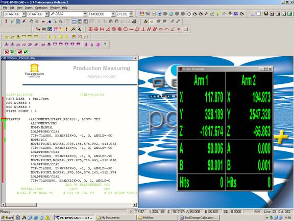
Switching to Master(Arm1), the Probe Changer calibration dialog box allows calibration of the Master tool changers:
Switching to the Slave(Arm2), the Probe Changer calibration dialog box now allows calibration of the Slave tool changer:
Jog Box Manual Tool Changing Controls
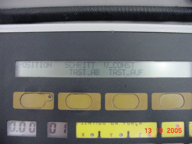
On Zeiss GPIB systems, the jog box looks as follows:
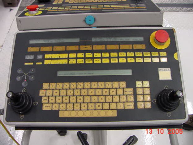
Use the TAST_AB and TAST_AUF buttons to disable and enable tool during manual changes.
For Zeiss UDP systems, the jog box appears as follows: -
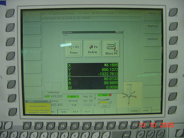
In this case (after you press F1 to enable the jog box, if necessary), use the second and third down buttons on the right-hand side to disable and enable the tool during manual changes.