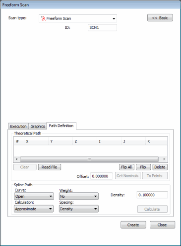

Freeform Scan dialog box
The Freeform Scan dialog box enables you to create any path on a surface. The scan will follow that path. This path is completely up to you: it can be curved or straight and have many or few hits.
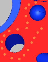
Example of a freeform scan before spline path:

Freeform scan before spline path
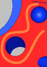
Example of a freeform scan after spline path:

Freeform scan after spline path
To Create a Freeform Scan
Click Advanced to display the tabs at the bottom of the dialog box.
Select items as desired on the Execution and Graphics tabs.
Select the Path Definition tab.
Define the theoretical path. Add hits to the Theoretical Path box. To do this, click on the surface of the part in the Graphic Display window. With each click, an orange point appears on the part drawing. Once you have five or more points, the Calculate button in the Spline Path area becomes enabled.
If needed, you can delete individual points. To do this, select them one at a time from the Theoretical Path area and press the Delete key.
If desired, select items in the Spline Path area, and then click Calculate. This creates a spline curve along the theoretical points you've defined and then recalculates the points in the theoretical path area to produce a smoother path for the probe to follow.
Click Create to generate the scan. If you have the PC-DMIS AutoWrist method enabled but don't have any calibrated tips, PC-DMIS will display a message informing you when it adds new probe tips that need calibration. In all other cases, PC-DMIS asks you whether it should use the closest calibrated tip to the needed tip angle or add in a new non-calibrated tip at the needed angle.