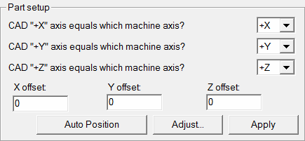
Part Setup area
The Part Setup area of the Part/Machine tab is useful when you create a measurement routine and the CAD coordinate system differs from the CMM part setup.
CAD "+X" axis equals list
This drop-down list allows you to set the relationship between the CAD X+ axis and the machine axis.
CAD "+Y" axis equals list
This drop-down list allows you to set the relationship between the CAD Y+ axis and the machine axis.
CAD "+Z" axis equals list
This drop-down list allows you to set the relationship between the CAD Z+ axis and the machine axis.
X offset box, Y offset box, Z offset box
These boxes allow you to enter the distance that PC-DMIS offsets the CAD drawing along the X, Y, or Z axis. PC-DMIS shifts the CAD drawing along the X, Y, or Z axis the specified distance. For example, if you enter in .5 in the X field, the entire CAD display in the Graphic Display window shifts the distance by .5 in the X direction.
All features created in the measurement routine do not shift along the axis with the CAD drawing.
Adjust button
The Adjust button opens the Adjust Part Setup dialog box.
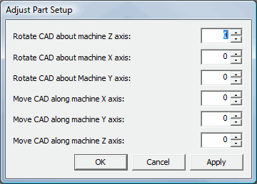
Adjust Part Setup dialog box
You can use this dialog box to rotate or move the CAD in increments about and along the machine's XYZ axes.
If you're rotating the CAD, then the values are in angle degrees. A value of 360 has the same effect as 0.
If you're moving the CAD, then the values are in the units of measurement that the measurement routine is in. For example, a value of 2 would mean 2 inches or 2 millimeters, depending on the units of measurement used by your measurement routine.
To adjust the CAD along or about an axis:
Click on the appropriate box.
Type a new value. PC-DMIS dynamically shows the adjustment in the Graphic Display window.
Click OK to accept the values and close the dialog box.
PC-DMIS maintains this adjustment unless you re-import the part's CAD model.
Auto Position button
The Auto Position button positions the part onto the graphical representation of the machine's table. Auto position best guesses where to position the part on the graphical representation. You can either let PC-DMIS determine where to put the part in relation to the CMM by using this function, or you can type your own positioning using the XYZ offset fields. (See "Defining Machines" in the "Defining Hardware" chapter for more information on setting up the graphical representation of the CMM.)
Apply button
When you click the Apply button, PC-DMIS immediately applies any changes made in the X, Y, or Z Offset fields. It also shifts the drawing along the appropriate axis (axes) while keeping the dialog box open.